4-32 LeeBoy 8520C Conveyor Paver
Operation
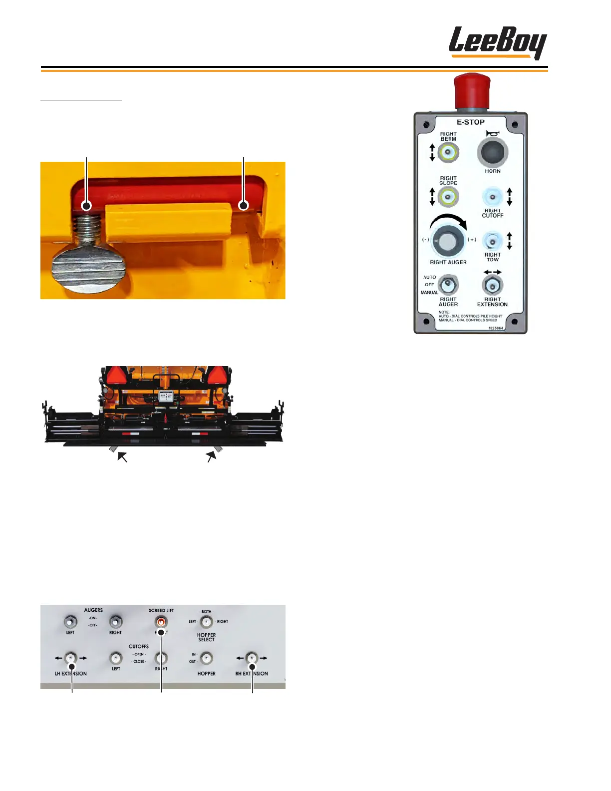
Screed Lock Pins
Screed lock pins (one on each side) adds additional
safety and stability during operation and transport.
(Figure 4-66)
Figure 4-66. Screed Lock Pin
NOTE: To set the depth, you can place small starter
blocks under the main screed while you make
adjustments. (Figure 4-67)
Figure 4-67. Starter Blocks Location
• Follow the instructions for heating the screed and
screed extensions. (Page 4-28)
• Extend or retract the screed extension using the
extension switch on the main control panel. (Figure
4-68)
• Use the Screed Lift/Float switch to lift the screen when
moving the paver to the starting position. Set the
switch to “oat” when paving.
Left
Right
Screed Lift/Float
Figure 4-68. Screed Switches
Figure 4-69. Screed Control Box
Adjust the screed while paving using the following
procedures:
1. Move paver to the starting position for paving.
2. Extend the screed extensions to the desired width.
3. Level the screed using the electric tow point gauge.
(Figure 4-63 on the previous page.)
• Refer to the elevation gauge (one on each side
of the paver for your convenience). Raise or
lower until the rod end of the cable is ush with
“0” on the gauge.
• While paving, refer to both gauges and make
minor adjustments if needed.
4. Null the screed on starting surface (or starter
blocks) using ight screws. Make adjustments as
needed while paving.
5. On the rst pass, turn the end gate depth screw to
lower the endgate until it is about 1/4-inch below the
screed. (Figure 4-70)
6. Turn the end gate tilt screw so the front of the
endgate tilts down slightly when the screed is lifted.
This will allow the endgate to set itself to the grade.
(Figure 4-68)
NOTE: Never allow the endgate to carry the weight of
the screed to prevent uneven compaction.
A remote control box
is also provided on
both sides to extend
or retract the screed
extensions, select
slope or berm, open
or close the cut-offs,
and turn the auger on
and off while paving.
Additional functions
on the 9-Function
control box include
berm and slope
controls, horn, E-Stop
button, auger dial,
and tow switch (left
box shown). (Figure
4-69).