103
4
3
1
2
F425
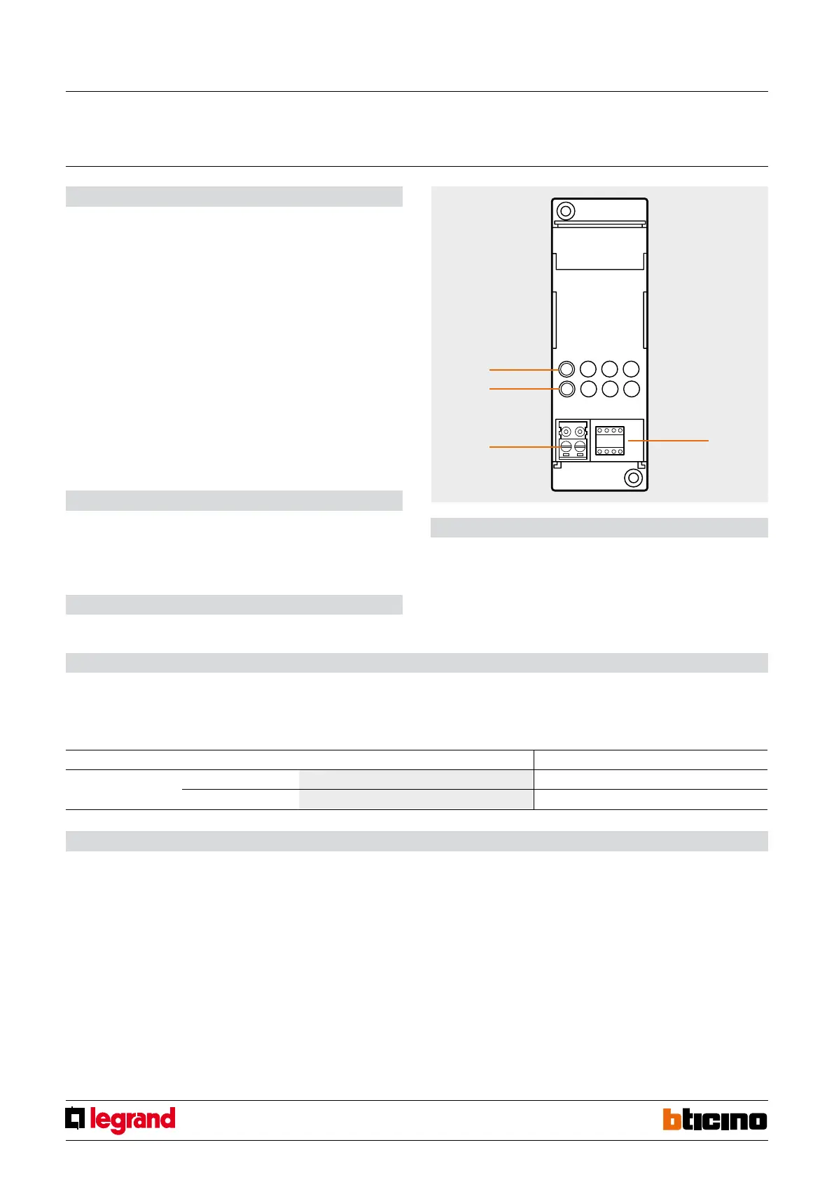
1. Configurator socket
2. BUS
3. Multicolour LED
4. Button
Legend
Description
The memory module is connected to the system and saves the status of all the devices.
This device is very useful in case of a black-out or short power cuts (minimum 400 mS),
because it can reset the status of all the lamps controlled by the system once the power
returns. The reset operations take about 10 seconds.
Just one memory module can be connected to the BUS for each system installed (i.e.
one for each power supply unit), unless two or more systems are being connected using
the SCS/SCS gateway (item F422) configured in physical expansion mode. In this case
just one is needed for all the systems connected together. The device must be put into
operation once the system is already installed and powered.
The multicolour LED indicates the status of the device:
- OFF: device too far from the power supply unit
- steady green: normal operation
- steady orange: system not yet acquired
- steady red: device exclusion phase
- blinking red: acquisition phase in progress
- blinking orange: incorrect or missing configuration
Technical data
- Power supply from SCS BUS: 27 Vdc from the BUS
- Operating power supply with SCS BUS: 18 – 27 Vdc
- Current draw: 5 mA
- Operating temperature: 0 - 40 °C
Dimensions
Size: 2 DIN modules
Configuration
If the device is installed in a My Home system it can be configured in two ways:
- PHYSICAL CONFIGURATION, inserting the configurators in position.
- Configuration via MYHOME_Suite software package, downloadable from
www.homesystems-legrandgroup.com; this mode has the advantage of offering many
more options than the physical configuration.
For a list of the procedures and their meanings, please refer to the instructions in
this sheet and to the "Function Descriptions" help section in the
MYHOME_Suite software package.
Memory Module
MQ00281-c-EN 07/06/2014
Address type Virtual configuration (MYHOME_Suite) Physical configuration
Point-to-point Room 0-10 A=0-9
Lighting point 0-15 PL=1-9
Programming
- Connect the memory module, switch the BUS ON and make sure that the loads of the
dimmers are connected and powered (all the loads must be OFF).
- Press the button on the front for at least five seconds, when the red LED comes on with
a steady light release the button. Release the button.
- Switch the loads which are not to be managed ON one by one (all the loads left OFF
will be managed).
- Press the device button within 30 minutes, the red LED will start to flash quickly to
show that the device is performing the learning procedure.
- After about 30 seconds the LED turns steady green to signal that the learning procedure
has ended and the memory module is operative.
- If the programming procedure has not been completed within 30 minutes, the LED
shines orange to signal that the system status has not been saved. At the end of the
programming procedure a test should be performed to check that the device is set
correctly.
- Switch on some of the controlled loads (i.e. those not explicitly excluded during the
programming procedure).
- Switch off, simulating a black-out, for at least 15 seconds.
- Switch back on again; after a few seconds the status of the controlled loads must be
reset (i.e. those which were ON before the black-out must switch back ON), while the
unmanaged loads must however remain OFF.
NOTES:
- The rolling shutter actuators are not managed.
- The timed switchings ON will be activated as simple switchings ON.
- It is important to configure the Memory module with a different A and PL address
to that of an actuator.
- For modifications to the system, repeat the save procedure.
WARNING:
The memory module is installed near the power supply unit (possibly in the same electri-
cal panel); the distance must however be no greater than 10 metres.


 To Next Page