104
C
N 1 N 2
N 1 N 2
5
4
2
1
3
F428
Description
This device lets you integrate traditional control devices (switches, pushbuttons, etc.) in
advanced systems with BUS operating logic.
Therefore, it is possible to extend the use of the Lighting Management system in rooms
where traditional systems are already present or in historic and prestigious rooms where-
by the complete or partial remaking of the electric system would entail heavy masonry
work. The old but valuable switch with its no longer compliant wiring can therefore con-
tinue to be used with it, as the connection to the load to be controlled is carried out safely
by connecting it with its respective interface with no-voltage contact.
Contact N1 controls light point PL1, contact N2 controls light point PL2.
It is possible to connect:
- Two N/O (normally open) and N/C (normally closed) traditional switches or buttons;
- A switch.
The device is fitted with 2 LEDs to signal contact closure, programming/deletion, and the
status of the control devices.
Technical data
Power supply via SCS BUS: 27 Vdc
Operating power supply with SCS BUS: 18 – 27 Vdc
Current draw: 9 mA
Dissipated power with max. load: 0.2 W
Dimensions
Size: 2 DIN modules
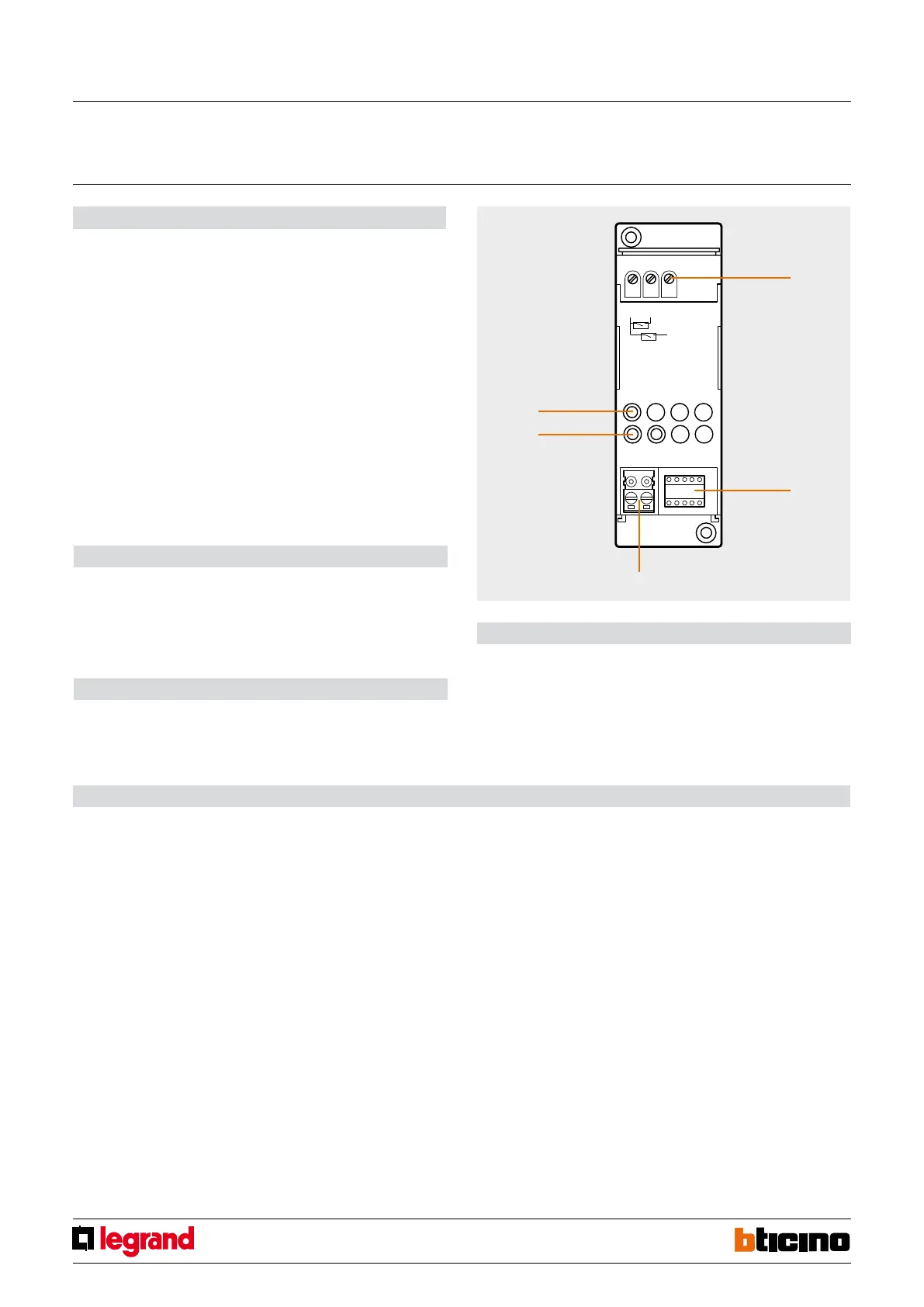
Legend
1. Clamps for connection to traditional devices
2. Configurator socket (note that this must only be used in My Home systems with the
physical configuration).
3. BUS
4. LED
5. Button
Contact interface
in DIN module
MQ00283-c-EN 07/06/2014
If the device is installed in a My Home system it can be configured in two ways:
- PHYSICAL CONFIGURATION, inserting the configurators in position.
- Configuration via MYHOME_Suite software package, downloadable from
www.homesystems-legrandgroup.com; this mode has the advantage of offering many
more options than the physical configuration.
For a list of the procedures and their meanings, please refer to the instructions in
this sheet and to the "Function Descriptions" help section in the
MYHOME_Suite software package.
When used as a component of the Lighting Management system, use the specific types
of configuration (Plug&go, Project&Download).
The interface consists of two independent control units, which are identified with the
positions PL1 and PL2 in the physical configuration and the term Module 1 and Module 2
in the MYHOME_Suite virtual configuration. The two units can send:
- commands to two actuators for two independent loads (On, Off or adjustment) identi
-
fied with the address PL1 and PL2 and the mode specified in M or;
- a command to the F420 scenario module;
- a double command intended for a single load (motor for blinds Up-Down, curtains
Open-Close) identified with the address PL1=PL2 and specified Configuration mode M.
The interface has an LED for indicating proper operation and three terminals for connec
-
tion to traditional devices such as:
Configuration
- two N/O (normally open) and N/C (normally closed) traditional switches or buttons;
- a switch.
List of Functions
The device performs the following functions:
1. LIGHT SWITCH
2. AUTOMATION CONTROL
3. DEVICE LOCKING/UNLOCKING
4. SCENARIO MODULE CONTROL
5. PROGRAMMED SCENARIO ACTIVATION
6. PLUS LIGHTING MANAGEMENT SCENARIO ACTIVATION
7. PLUS PROGRAMMED SCENARIO ACTIVATION
8. SOUND SYSTEM CONTROL
See the following pages for the configuration procedures.


 To Next Page