199
Z N
M
O
D
A
U
X
3440
Conguration
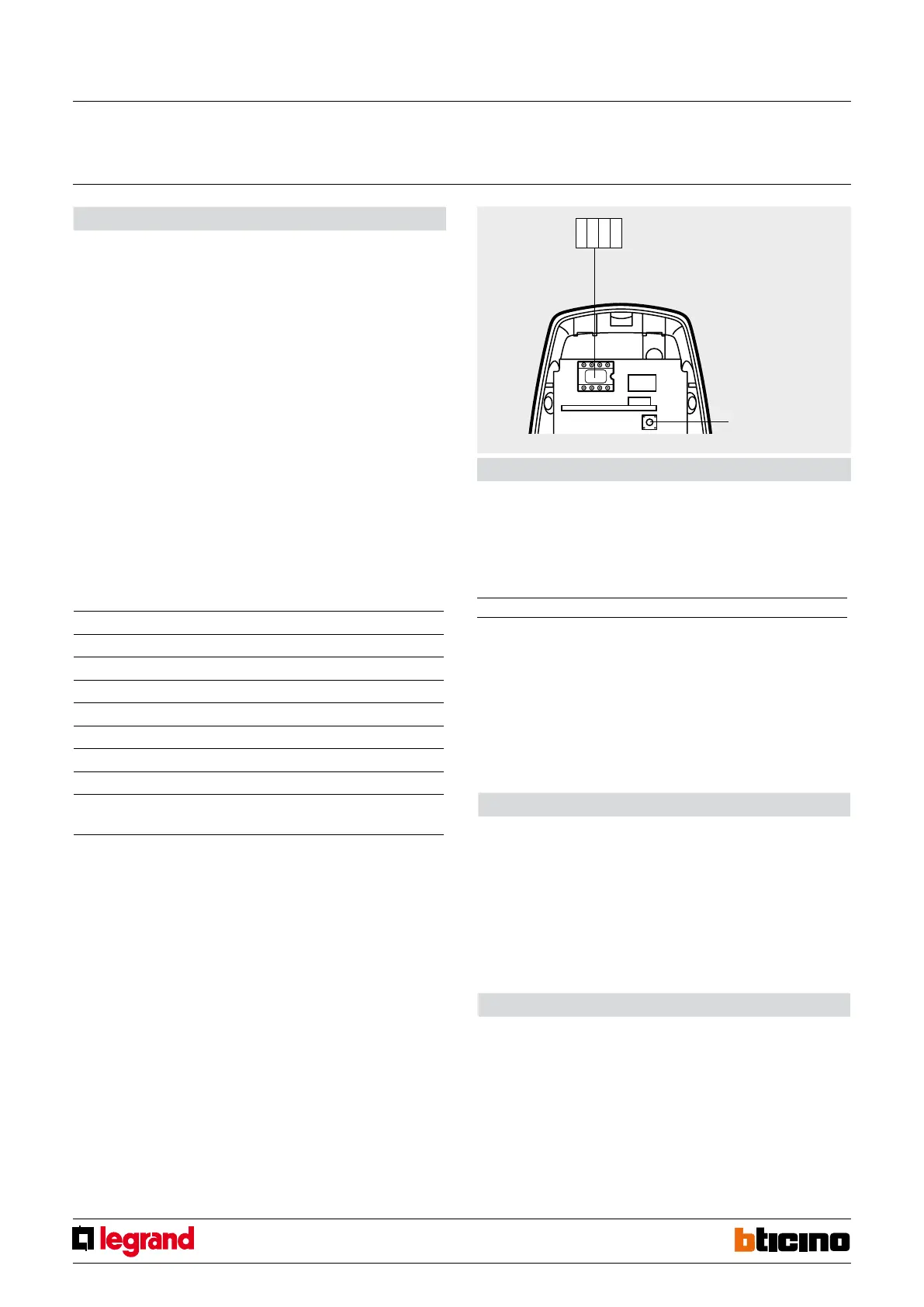
Infrared radio detectors require assigning of the zone they belong to, of the progressive
sensor number within the zone, setting of the detection mode and the allocation of an
auxiliary prealarm channel.
WARNING: the conguration operations must be performed with the battery disconnected.
Z
This congurator assigns the number of the appropriate zone to the detector.
Congurator 1 assigns zone 1 to the detector, congurator 2 assigns zone 2 and so on to
a maximum of 8 zones.
N
This congurator assigns the progressive number of the detector inside the appropriate
zone.
Congurator 1 identies the rst detector, congurator 2 identies the second and so on
to a maximum of 9 sensors (IR detectors and contact interface) for each of the 8 zones.
MOD
This congurator sets the sensor detection mode.
It can be used, for EXAMPLE, when the device is directed towards a possible source of
disturbance (window or radiator), and its position cannot be changed.
Pairing IR radio sensors
1. Switch the system to “maintenance” mode.
2. Press the programming pushbutton of the radio receiver for ve seconds, until the red
LED comes on.
3. Press the sensor tamper contact twice.
4. If the pairing of the device has been performed correctly, the red LED of the radio
receiver will go o.
If this does not happen, repeat the procedure from step 3. If the LED ashes, it means
that the device memory is full.
5. To pair other devices, repeat from step 2.
6. Perform self learning of the system from the central unit.
7. Exit “maintenance” mode.
Cancelling the IR radio sensors
1. Switch the system to maintenance mode.
2. Remove the power supply from the receiver.
3. Press and hold the programming pushbutton while reconnecting the power supply
to the radio receiver.
4. After 5 seconds the LED ashes orange. If the pushbutton is released at this time, only
the remote controls are cancelled. After 10 seconds the LED starts ashing quickly.
If the pushbutton is released now, only the sensors are cancelled.
5. After releasing the pushbutton, the LED becomes xed orange. When the LED goes
o, cancellation has been completed.
6. Perform self-learning of the system from the central unit and exit “maintenance” mode.
ON timed control
For this mode, congure in the Z and N positions of the detector the addresses A and PL
of the actuator to control respectively.
To the MOD position connect the ON congurator to enable the time delay function.
The switching ON period is set by connecting numerical congurators 1 to 9 to the AUX
position as shown in the following table:
NOTE:
1) Use the pulse counter function to avoid false alarms caused by thermal variations
(radiators etc.).
2) Feature available on central units produced starting from week 08W06.
AUX
This congurator activates the prealarm function and assigns an auxiliary channel (AUX).
To enable and use the AUX channels, refer to the description for wired IR detectors.
NOTE: When the system is armed, the detector generates a normal burglary alarm.
AUTOMATION – TIMED CONTROL mode:
Passive IR detectors can generate and send an ON timed control directly to one or more
actuators of the automation system.
AUTOMATION mode – GENERIC CONTROL USING AUXILIARY CHANNELS
In this case, the control intended for the actuator is managed by a control device, item
H/L4651M2 or AM5831M2, which, based on its own operating mode, set in its own M
position, activates the actuator with address set in A and PL.
The communication between the detector and the associated control device item
H/L4651M2 or AM5831M2 is established by dening an auxiliary channel that has been
congured in the IR detector by connecting the AUX congurator to the MOD position
and specifying, with numeric congurators 1-9 in the AUX position, the number of the
auxiliary channel. Obviously, in order to univocally set the auxiliary channel, also the
AUX position of the control must have the same congurator as the IR detector.
Congurator Mode
0 1
st
level of sensitivity (1 high sensitivity impulse)
1 1
st
level of sensitivity (pulse counter
1
- high sensitivity)
2 2
nd
level of sensitivity (1 high sensitivity impulse)
3 3
rd
level of sensitivity (1 high sensitivity impulse)
4 1
st
level of sensitivity (1 high sensitivity impulse) delayed
2
5 1
st
level of sensitivity (pulse counter
1
- high sensitivity) delayed
2
6 2
nd
level of sensitivity (1 high sensitivity impulse) delayed
2
7 3
rd
level of sensitivity (1 high sensitivity impulse) delayed
2
9 The device sends an auxiliary type alarm through the specied
channel in the AUX position only when the system is armed
AUX 1 2 3 4 5 6 7 8 9
Time 1 min. 2 min. 3 min. 4 min. 5 min. 15 min 30 sec. 0.5 sec. 2 sec.
Congurator
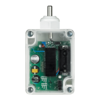
socket
Tamper/learning
Radio IR detector
MQ00055-c-EN 21/10/2013


 To Next Page