213
1
4
2
6
5
7
3
Z1
N1
MOD1
Z2
N2
MOD2
3480
Conguration
This interface module requires - for each of the two contact lines separate from each
other - the allocation of the assigned zone Z, the progressive number N of the detectors
situated in the same zone, the setup of the MOD protection mode of the contact line.
Z1
This congurator assigns the number of the assigned zone of the NC/NO magnetic
contact connected to line 1.
Congurator 1 gives the contact the assignment to zone 1, congurator 2 gives the
assignment to zone 2 and so forth, up to a maximum of 8 zones.
Z2
As above, for contacts connected to line 2.
N1
This congurator assigns the progressive number of the NC magnetic contact within the
zone determined in position Z1.
Congurator 1 identies the rst detector, congurator 2 identies the second, and so
forth, up to a maximum of 9 contacts for each of the 8 zones.
N2
As above, for contacts connected to line 2 (zone Z2).
MOD1 and MOD2
In this position a congurator is inserted for selecting the operating mode of the
interface according to the type of contact or detector connected to the two lines.
The interface can operate in two modes:
- as interface for the management of alarm contacts, system connection
pushbutton, and auxiliary channel generation;
- as interface for the management of technical alarms.
Technical data
- Power supply from SCS BUS: 27 Vdc
- Max. absorption: 5 mA
- Operating temperature: 5 – 40°C
Dimensional data
- Size: 2 Basic modules
Description
This interface is used to connect 2 independent contact lines that can be balanced by
means of a resistance, and which tripping can be delayed, as well as one tampering
protection line. It can be used to achieve centralisation of all interfaces inside junction
boxes. A LED on the interface conrms appropriate operation of the device during the
system test procedure, and the tripping of the burglar-alarm system, when the system
is armed. This interface gives the possibility of connecting the alarm system to a sensor
line (that can be balanced with resistance, and/or which intervention can be delayed)
requiring 12V V power supply.
Z1
N1
MOD1
Z2
N2
MOD2
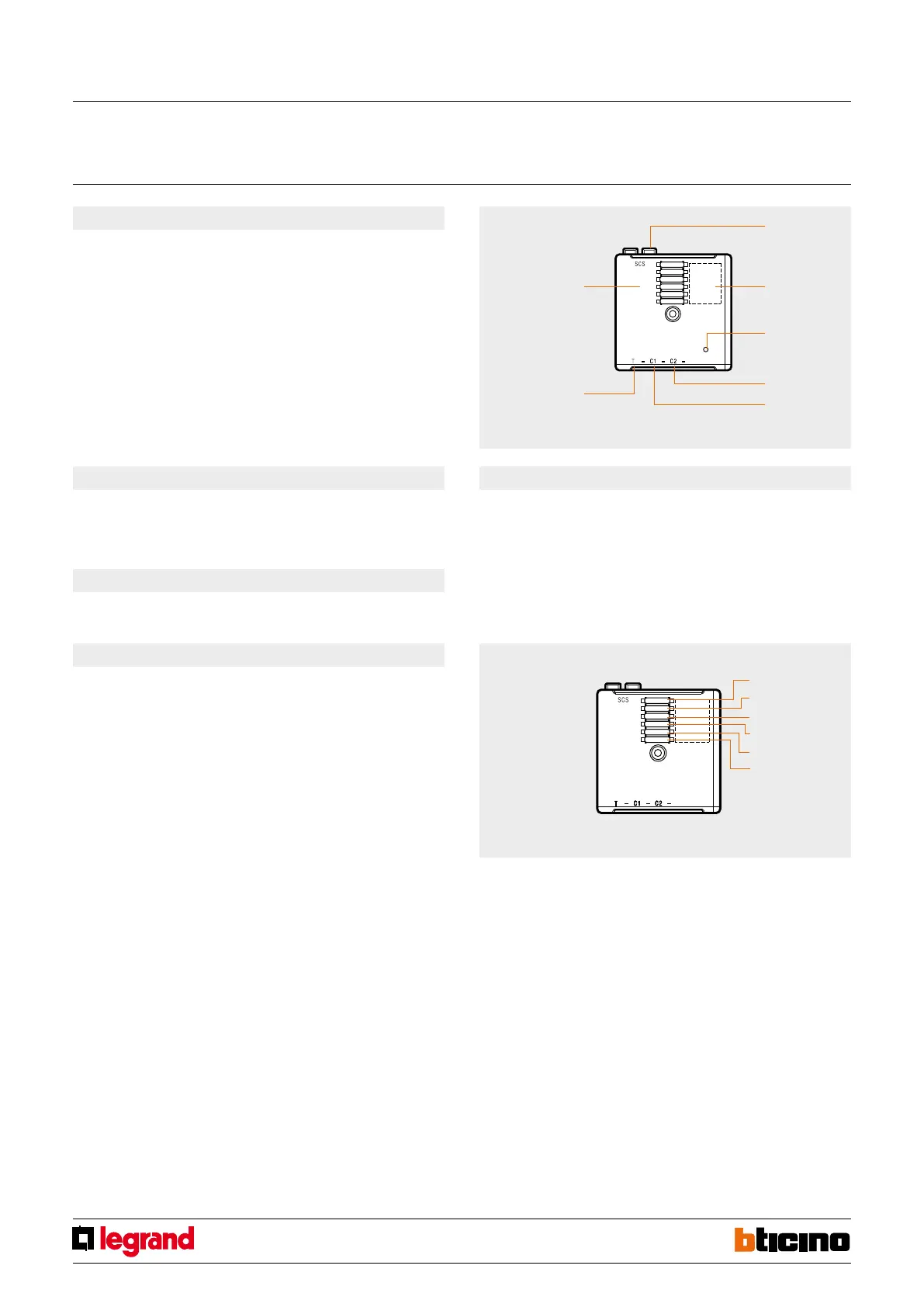
Legend
1. BUS;
2. Congurator socket;
3. Line activated LED;
4. Contact line 2;
5. Contact line 1;
6. Tamper line;
7. Anti-tamper device.
Front view
Contact interface
MQ00045-d-EN 28/04/2014


 To Next Page