217
1
2
3
4
5
6
7
Z
N
MOD
3480V12
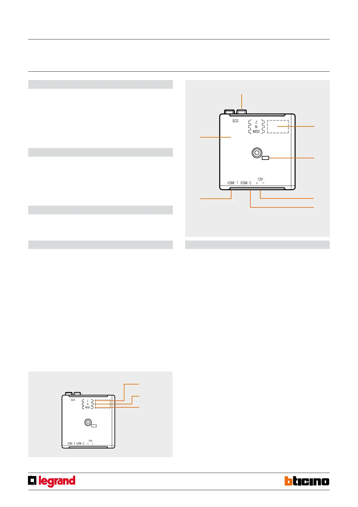
Legend
1. BUS;
2. Configurator socket;
3. Line activated LED;
4. 12 V power line;
5. C contact line;
6. Tamper line;
7. Device tamper protection against opening
Description
This interface gives the possibility of connecting the alarm system to a sensor line (that
can be balanced with resistance, and/or which intervention can be delayed) requiring
12 V power supply.
Produced in the basic modular version, the device can be used when centralizing all the
interfaces in junction boxes. A LED on the device confirms the appropriate operation
of the same during the system test procedure, and the tripping of the burglar-alarm
system, when the system is armed.
Power supply from SCS BUS: 27 Vdc
Max. absorption: 5 mA to which the absorption of the sensor
connected must be added
Operating temperature: 5 – 40 °C
Output: 12 V Max 50 mA
Technical data
Size: 2 Basic modules
Dimensional data
The interface requires the allocation of the zone Z it belongs to, of the N progressive
number of the sensors within the same zone, and the setting of the MOD contact line
protection mode.
Z1
This congurator assigns the number of the assigned zone of the NC magnetic contact
connected to line 1.
N1
This congurator assigns the progressive number of the NC magnetic contact within the
zone determined in position Z1.
MOD
In this position a congurator is inserted for selecting the operating mode of the
interface according to the type of contact or detector connected to the line. It is possible
to create a balanced and unbalanced protection line, with the possibility of generating
the alarm with a delay, as for zone 1. For the details of the various operating modes, refer
to the table below.
Configuration
1
2
3
4
5
6
7
Z
N
MOD
12 v contact interface
MQ00480-b-EN 24/04/2014


 To Next Page