218
N.C. N.C. N.C.
N.C. N.C. N.C.
1
3480V12
If the contact interface is used in conjunction with the temperature control system to
optimise energy saving, two dierent types of congurations will be possible:
- Use in the temperature control system only: The contact interface is directly connected
to the temperature control BUS It autonomously and independently manages
the contact line. Follow by connecting the AUX congurator to the MOD sockets.
Then congure the Z and N sockets, in order to assign the address from 1 to 99 to
the device within the system. The coupling between the interface contact line and
the temperature control zone must be performed using the TiThermo application.
For more information refer to the MY HOME Temperature control guide.
- Use of a burglar-alarm system integrated with the Temperature control system: in this
case, the contact interface is connected to the burglar-alarm system BUS only, and
communicates with the temperature control system BUS through the F422 interface.
The interface must be congured in Z and N following the requirements and features of
the burglar-alarm system; only congurators with values 4 to 7 must be connected to
the MOD position, corresponding to the management of NC contacts with generation
of AUX event (see tables above). Also in this case, the actual coupling between the
interface contact line and the temperature control zone must be performed using the
TiThermo application. For more information refer to the MY HOME Temperature control
guide.
Configuration
Energy saving management with Temperature control
Congurator Sensor connected
none NC contact
1 NC contact - balanced
2 NC contact - delayed *
3 NC contact - delayed * - balanced
4 NC contact and AUX event generation
5 Balanced NC contact and AUX event generation
6 Delayed NC contact and AUX event generation
7 Balanced delayed NC contact and AUX event generation
Specic mode for connection to wired rolling shutter sensors
Congurator Sensor connected Pulses (*)
8 Rolling shutter rope sensor -
delayed*
12 (approx 20 cm)
9 Rolling shutter rope sensor -
delayed*
25 (approx 45 cm)
Note (*): Follows the delay set on the central unit:
this function is operative only with central units with display. With ush mounted 3
module central units, the interface must be allocated to ZONE 1, with a time delay set
(see central unit conguration).
Note (**): pulses generated by the sensor depending on the degree of opening of the
window, in cm, before the alarm is generated.
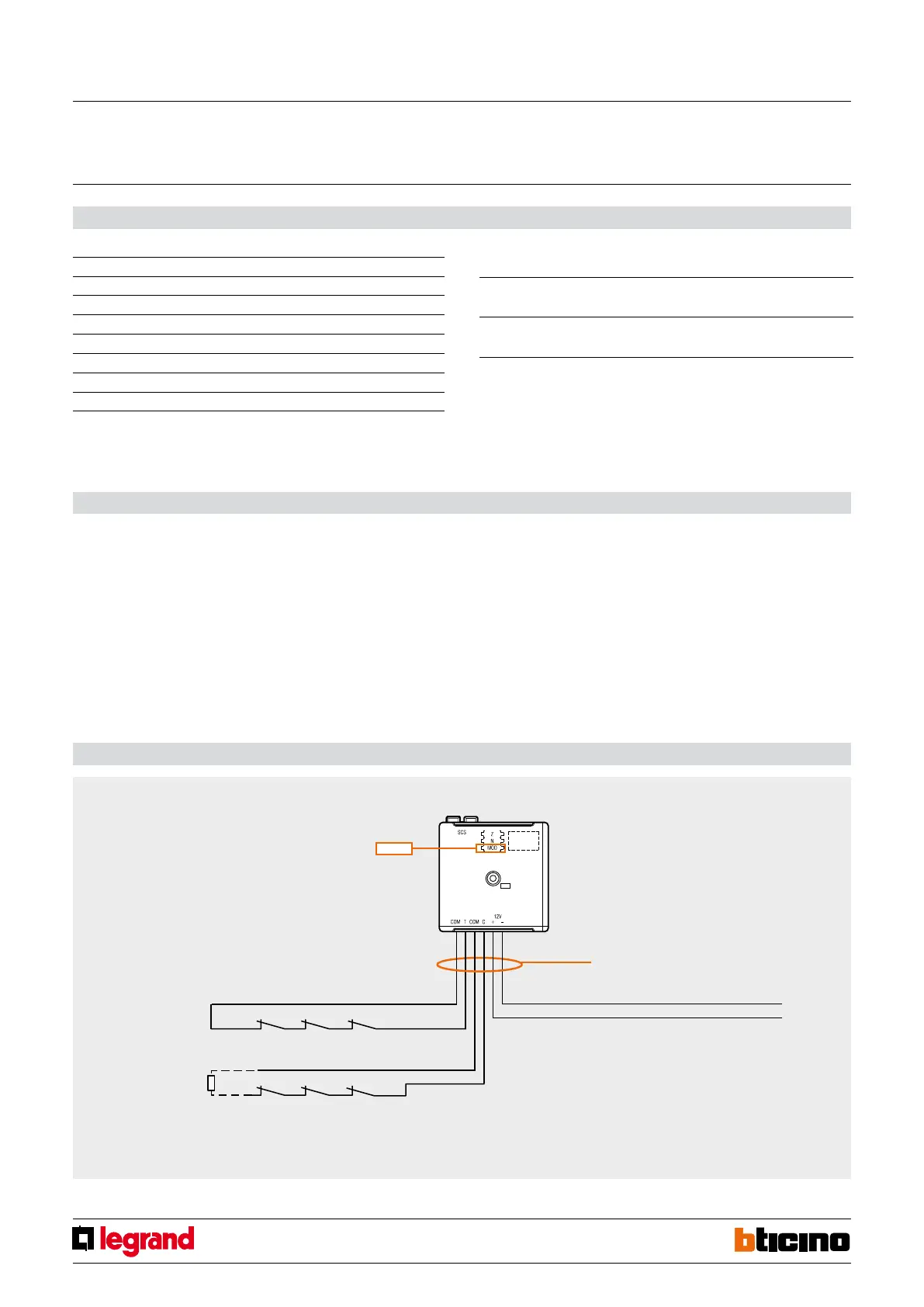
Wiring diagram
Sensor tamper
Balance resistance
100 kΩ ± 5% 1/4 W
Twisted, unshielded cable, with 30 metre
maximum length.
* Do not install more than 3 rope sensors on each line
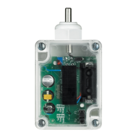
12 v contact interface
MQ00480-b-EN 24/04/2014


 To Next Page