308
NL
1
2
5
34
C1 C2 C3 C4
1
23
4 5
C1
C2
C3
C4
M
M
1
3
5
2
BUS
4
NL
1
2
5
34
C1 C2 C3 C4
1
23
4 5
C1
C2
C3
C4
M
1
BUS
2
F430/4
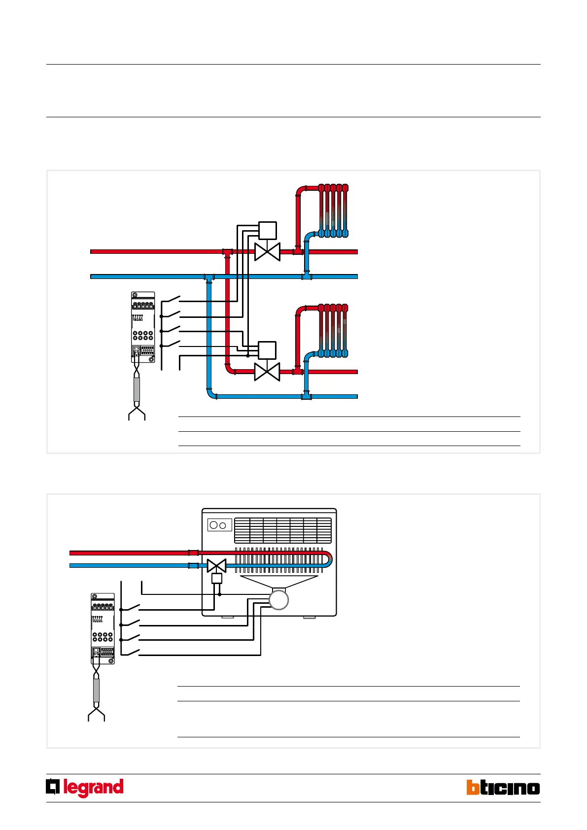
Example 2
Conguration and connection of the 4 interlocking relays actuator for the control of two solenoid valves, with opening and closing control in zones 2 and 3.
The progressive zone number is 2.
Legend
1. actuator
2. zone 2 solenoid valve
3. zone 3 solenoid valve
4. zone 2 radiator
5. zone 3 radiator
OPEN
CLOSE
OPEN
CLOSE
Example 3
Conguration and connection of the 4-relay actuator, for the control of a 3 speed fan-coil in zone 69. The progressive zone numbers is 4.
Legend
1. actuator
2. 2-pipe 3-speed fan-coil
SOLENOID VALVE
MIN. SPEED
MEDIUM SPEED
MAX. SPEED
Note
If a fan-coil is used in a heating system, it should be
ensured that the fan does not operate when the water
is cold, to avoid cooling the room rather than heating it.
Some fan-coils are tted with a water temperature probe
for this function. If a fan-coil without tted sensor is used,
an eective solution is to install an immersion thermostat
on the water return pipe. The contact of the thermostat
controls a remote switch, to which the fan-coil power
supplies are connected.
Actuator conguration
ZA ZB1 ZB2 ZB3 ZB4 N RL1/C1 RL2/C2 RL3/C3 RL4/C4
0 2 2 3 3 2 OPEN CLOSE OPEN CLOSE
Actuator conguration
ZA ZB1 ZB2 ZB3 ZB4 N RL1/C1 RL2/C2 RL3/C3 RL4/C4
6 9 9 9 9 4 Valve Minimum
speed
fan
Medium
speed
fan
Maximum
speed
fan
Actuator 4 relays
MQ00185-c-EN 29/04/2014
 Loading...


