334
1
2
3
5
4
6
3522N
Description
The device detects, counts and processes the information (water, gas, etc.) received from
meters with pulse outputs, and makes it available to the SCS BUS.
The processing and accounting functions are:
- calculation of the instantaneous value (flow rate - unit/h): the distance between two
consecutive pulses. If the distance between two pulses exceeds 30 seconds, the value of
the flow rate will be 0. The formula to calculate the flow rate is as follows: Flow rate =
(3600 / distance between two pulses) * (multiplication factor/divisor). For the details,
please see the "Configuration" chapter
.
- saving the following data to the internal memory:
- Number of pulses accumulated on an hourly basis for the last 12 months
- Number of pulses accumulated on a daily basis for the past 2 years
- Number of pulses accumulated on a monthly basis for the past 12 years.
The interface can be installed inside flush mounted boxes, behind traditional devices or
even in distribution boards, without using a DIN rail space.
In order to allow the device to archive consumption information, the system must be
fitted with a device capable of supplying current date and time information (e.g. Touch
Screen). If this information is not available, the pulse counter interface will be unable
to archive the data, but will continue calculating the instantaneous values (flow rate).
The pulse counter interface has a bay for 5 configurators: A1, A2, A3, MUL and DIV.
NOTE: The counter cannot detect any pulses shorter than 60ms (30 ms pulse length, 30
ms pause).
Technical data
Operating power supply with SCS BUS: 21 – 27 Vdc
Power consumption on standby: 17 mA max
Operating temperature: 0 – 40°C
Dimensions
Basic module: - Length: 40 mm
- Width: 40 mm
- Height: 23 mm
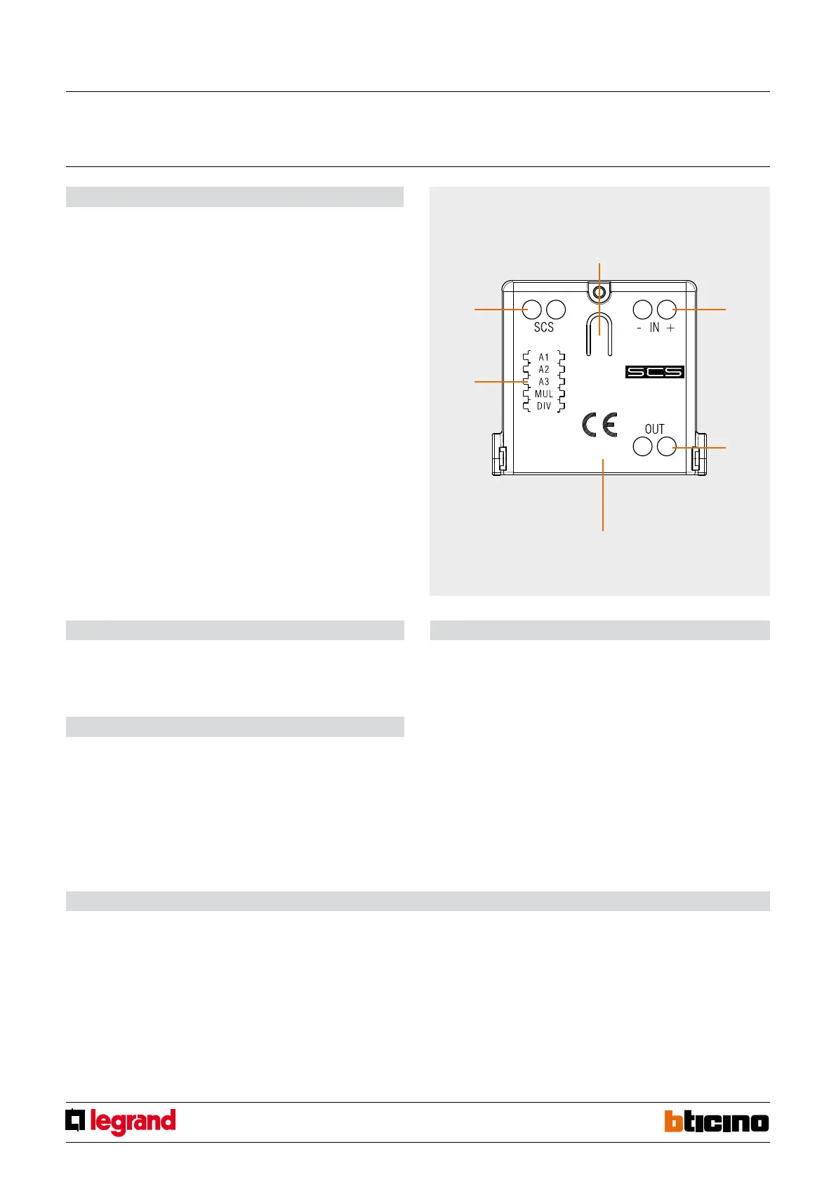
Front view
Legend
1. Pulse input
The stated polarity must be observed with Open drain and Open collector counters.
2. Opto-isolated pulse input repetition
3. LED
steady green: device ON
red ON steady/OFF steady: pulse detection (each time a pulse is received the status
passes from ON steady to OFF steady and vice versa).
flashing green 500ms/500ms: problem on the bus (low BUS voltage or voltage drop
detected).
red and green flashing irregularly: configuration error.
flashing red and green 128ms/128ms: not configured.
4. Button
5. Configurator socket
6. SCS BUS connection
Configuration
The device can be configured in two ways:
- Physical configuration, inserting the configurators in the sockets:
A1/A2/A3 device address (A1 for hundreds, A2 for tens, A3 for units).
The maximum number of configurable addresses is 127.
MUL (multiplication factor to be applied to each pulse received), DIV (indicates the
number of pulses emitted by the meter before the pulse counter interface saves a pulse).
- Virtual configuration via MYHOME_Suite software package, downloadable from www.
homesystems-legrandgroup.com; this mode has the advantage of offering many more
options than the physical configuration.
For a list of the procedures and their meanings, please refer to the instructions in this
sheet and to the "Function Descriptions" help section in the MYHOME_Suite software
package.
Pulse counter interface
MQ01007-a-EN 07/06/2014
 Loading...


