335
BUS SCS
3522N
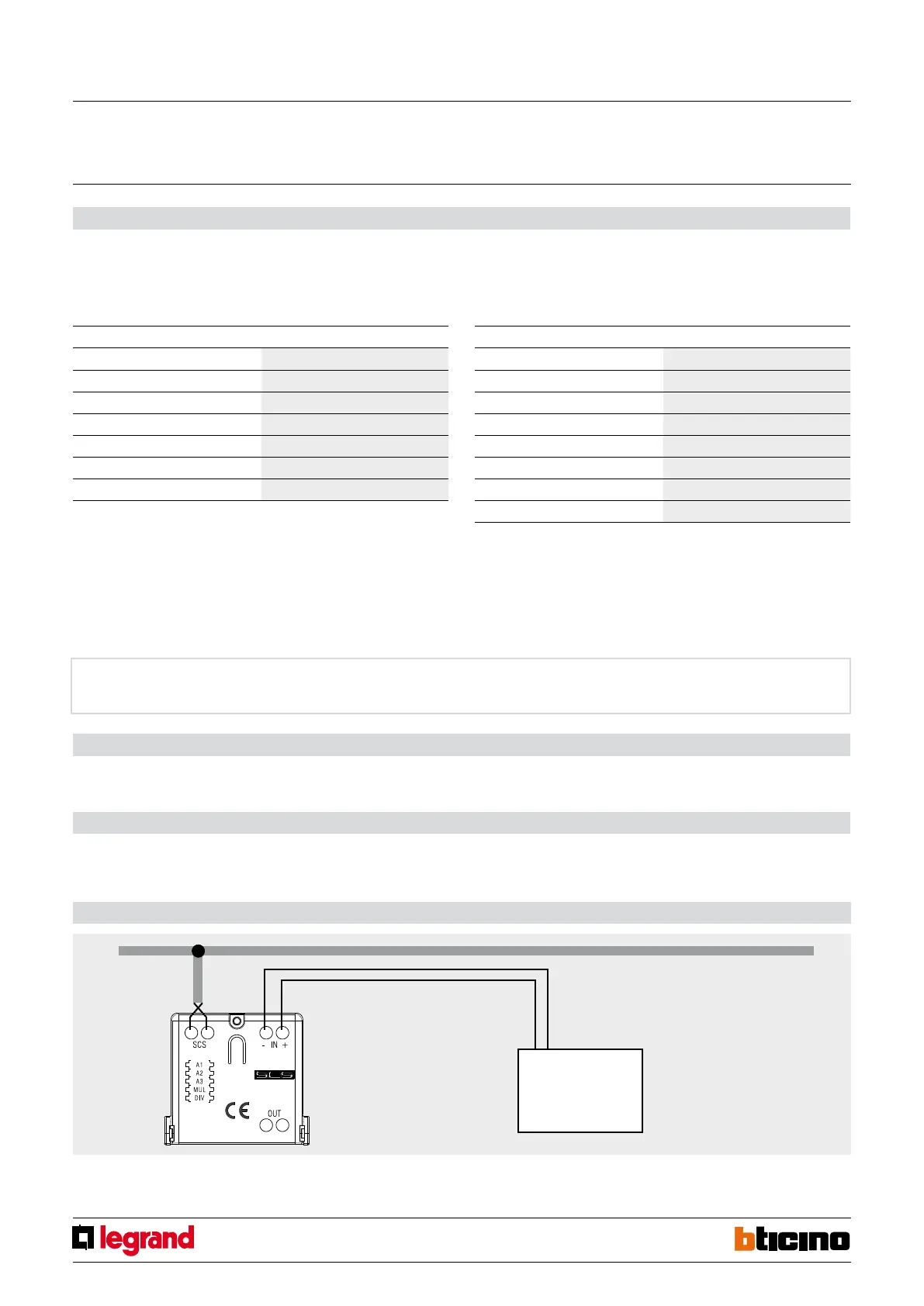
Wiring diagrams
Counter
with pulse output
MQ01007-a-EN 07/06/2014
Pulse counter interface
Physical configuration
1.1 MUL position
The configurator in the MUL position specifies the multiplication factor to be applied to
the single pulse, as specified in the following table:
1.2 DIV position
The configurator in the DIV position specifies how many pulses must be measured by
the interface to produce a valid effective pulse for energy accounting, as specified in the
following table:
Virtual configuration
For the configuration mode, please refer to the MYHOME_Suite software package and to
the "Function Descriptions" help section within the application itself.
Procedure for deleting measured data
At any time you can reset the cumulative value of the number of pulses measured by the
interface. The procedure is as follows:
1. Press the button on the interface for at least 20 seconds and release it when the two
green and red LEDs flash.
2. The data of the readings saved by the interface are deleted.
Configurator on DIV Divisor
0 /1
1 /10
2 /100
3 /1000
4 /2
5 /20
6 /200
7 /2000
Configurator on MUL Multiplication factor
0 x1
1 x2
2 x5
3 x10
4 x20
5 x50
6 x100
WARNING: The pulse counter interface must be installed as close as possible to the power supply
unit, to ensure a high BUS voltage and enable correct management of memory savings in case of
power failure. If the supply voltage is insufficient (below 21 Vdc), the pulse counter interface will
cause the green LED to flash to signal the installation error. The device will work properly, but will
not guarantee correct saving and recovery of data in case of BUS failure.
The MUL and DIV configurator can be used simultaneously to meet every specific need.
NOTE: Observe the polarity with
Open drain and Open collector
counters.
EXAMPLE: The water volume meter provides 1 pulse every ten litres. We want to save the litres to
the pulse counter interface and make them available on the SCS BUS. We put configurator 3 into
position MUL. The pulses measured by the counter are multiplied by 10 and saved in the pulse
counter interface.
EXAMPLE: The water volume meter provides 1 pulse every half litre. We want to save the litres to
the pulse counter interface and make them available on the SCS BUS. We put configurator 4 into
position DIV. For every two pulses the meter emits, the pulse counter interface saves one pulse.
WARNING: The maximum number of pulses the interface can save in 1 h is equal to 65536 *
(divisor / multiplication factor).
FOR EXAMPLE: The counter provides 1 pulse per hundred litres and we want to save the litres
to the memory of the pulse counter interface. We configure MUL=6 and DIV=0. The maximum
number of pulses the meter emits must be 65536 * (1/100) = 655 pulses/h. Should this value be
exceeded, the pulse counter interface would in any case make 655 pulses/h available on the BUS.
 Loading...


