343
1
2
4
7
8
1
5
3
5
6
F522
Description
The device is an actuator with 1 bistable relay sensor with zero crossing functionality,
intended for the load control and/or automation functions.
In load control mode:
The actuator will be given a priority indicating the tripping order that will be followed by the
F521 load control central unit (e.g. Priority 1 will be the first load disabled if the threshold is
exceeded). The actuator is fitted with a current sensor for the measurement of the controlled
load consumptions, as well as for the display of the instantaneous consumption, and two
energy totalizers that can be reset by the user at any time.
The device also measures the residual current to allow displaying the diagnostics on the user
interfaces (this feature is only available by connecting the optional external toroid 3523 to
the actuator).
Using the forcing pushbutton it will be possible to re-enable the load for 4 hours after
disabling by the central unit.
In automation mode, the actuator can perform the following functions:
- All operating modes that can be configured on the control devices, with the exception of
those requiring the use of two interlocked relays (rolling shutters).
In mixed load control and automation mode, the following rules are followed:
The local button performs the load control management function (forcing/end of forcing)
- If the load is ENABLED or FORCED, the status of the relay follows the commands of the
Automation system.
- If the load is DISABLED by the load control central unit, the status of the relay does not
follow the commands of the Automation system, but can only be re-enabled by a command,
ENABLING or FORCING, from load control management.
During disabling, the actuator keeps the statuses requested by the Automation commands in
memory. After RE-ENABLING the relay is placed in the status required by the last automation
command.
This function has been conceived for applications where the load control management func
-
tion is implemented, with the need, via automation commands, of performing hourly load
scheduling. If during the DISABLING stage the relay is switched OFF due to the scheduling
settings, when re-enabling takes place it will stay switched OFF.
The bistable relay enables preserving the status of the load even if there is no voltage on the
SCS BUS (and subsequent device reset).
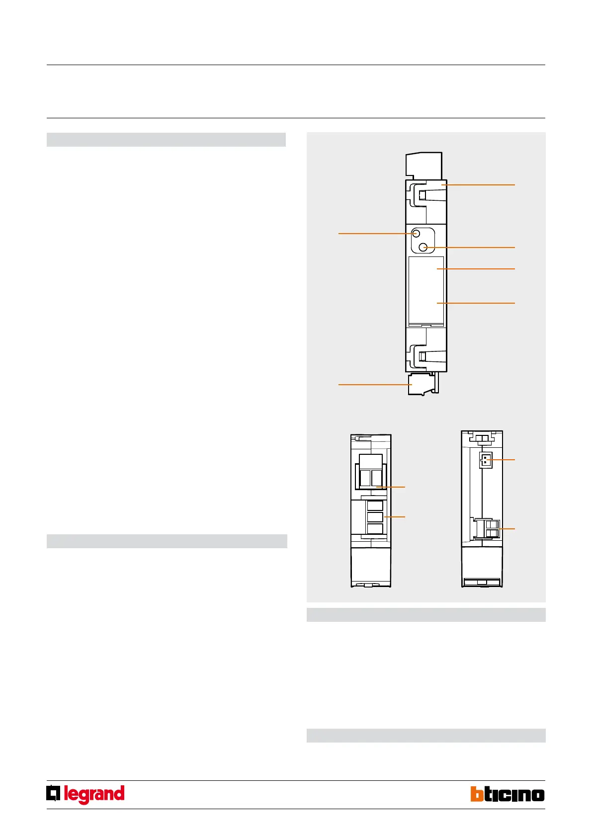
Front view
View from above View from below
Legend
1. 230 Vac connection
2. Button for load forcing
3. Virtual configuration pushbutton (future use)
4. Configurator socket
5. BUS connection
6. User interface LED, SEE TABLE
7. Toroid connection (3523) to measure the residual current
8. Load connection
Technical data
Operating power supply
with SCS BUS: 18 – 27 Vdc
Current draw: 30 mA max
Range of measurement: 200 mA – 16 A
Operating temperature: 0 – 40°C
Power/Consumption of driven loads: Incandescent lamps and halogen lamps 10 A / 2300 W
LED lamps and compact fluorescent lamps 500 W /
Max 10 lamps
Linear fluorescent lamps and electronic transformers
4 A / 920 W
Ferromagnetic transformers 4 A cosφ 0.5 / 920 VA
Dimensions
1 DIN module
MQ00361-d-EN 09/06/2014
Actuator 16A with current sensor
 Loading...


