359
3
2
4
5
1
GATEWAY
Description
This device represents the interface between the MY HOME Temperature control system
and the Climaveneta IDRORELAX system.
The item allows the passage of the controls produced by the bus system toward the
fan-coil. It is necessary to consider one for each fan-coil, thus correctly scaling the bus
system as regards absorption and conguration.
As a matter of fact, the item is housed inside the fan-coil during the production phase
thus it is already connected to it by means of the connector located at the top of the front
side. Basically, after performing the hydraulic and electrical connection, you will only
need to connect the bus using the appropriate clamp.
Conguration
The item is the interface that can be found on the Climaveneta Chiller and the Fan-Coil. It
is necessary for the connection to the temperature control BUS. As for the actuators, also
for this device it will be necessary to connect to the ZA and ZB sockets two congurators
that identify the address, and the number of the zone it belongs to.
In practical terms, the operation is the same as the one performed for the probe, during
the denition of the zone. A probe and a Gateway belonging to the same zone will
require the same numeric congurators in the ZA and ZB sockets.
The TYPE socket must be congured to indicate the type of load to be managed.
If the Gateway manages a Fan-Coil, the numeric congurator 0 must be connected to the
TYPE socket, If it manages a Chiller, numeric congurator 1 will be required.
When the Gateway is congured for the management of the Chiller, it will be possible to
read the external temperature coming from the Climaveneta Chiller.
This information may be simply displayed, or , in case the system is managed by the 99
zone central unit, item 3550, it may be used to program and activate temperature control
automations.
Depending on needs, temperature control automations may activate certain actions with
certain temperature conditions. For example, in case thresholds that may be manually
set are exceeded, the temperature control system may automatically switch the settings
from summer to winter, and vice versa. On the front of the interface are four sockets
dedicated to the congurators:
ZA ZB zone address
N progressive zone number
TYPE type of load to control (Fan-Coil or Chiller)
NOTE: Gateway is a Climaveneta product that can already be found on fan-coils. For
further information and for the technical documentation of the Climaveneta IDRORELAX
system, contact the Customer Service Toll Free number 800.019.190 (8.30-12.30
and 14.00-18.00 Monday to Friday - calls are free of charge).
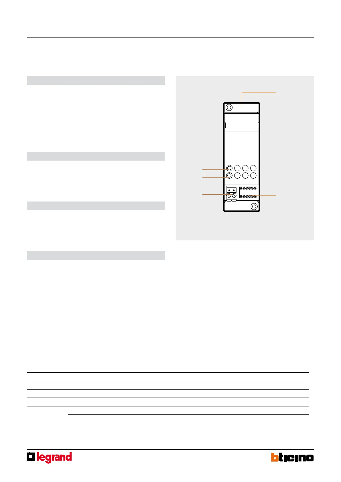
Legend
1. Connector: for Climaveneta fan-coil connection
2. Congurator socket: socket for the congurators
3. Removable connector clamp for SCS BUS connection
4. LED: not used.
5. Key: not used.
Technical data
- Power supply from SCS BUS: 27 Vdc
- Operating power supply with SCS BUS: 18 – 27 Vdc
- Max. absorption: 18 mA
- Operating temperature: 0 – 40 °C
- Size: 2 DIN modules
Congurator summary table:
Socket Function Congurator
ZA Zone address 0 – 9
ZB Zone address 0 – 9
N Progressive zone number 1 – 9
TYPE Fan-Coil management 0
Chiller management 1
Front view
Gateway
MQ00186-c-EN 29/04/2014