443
353200
BT00606-a-EN
TECHNICAL SHEETS
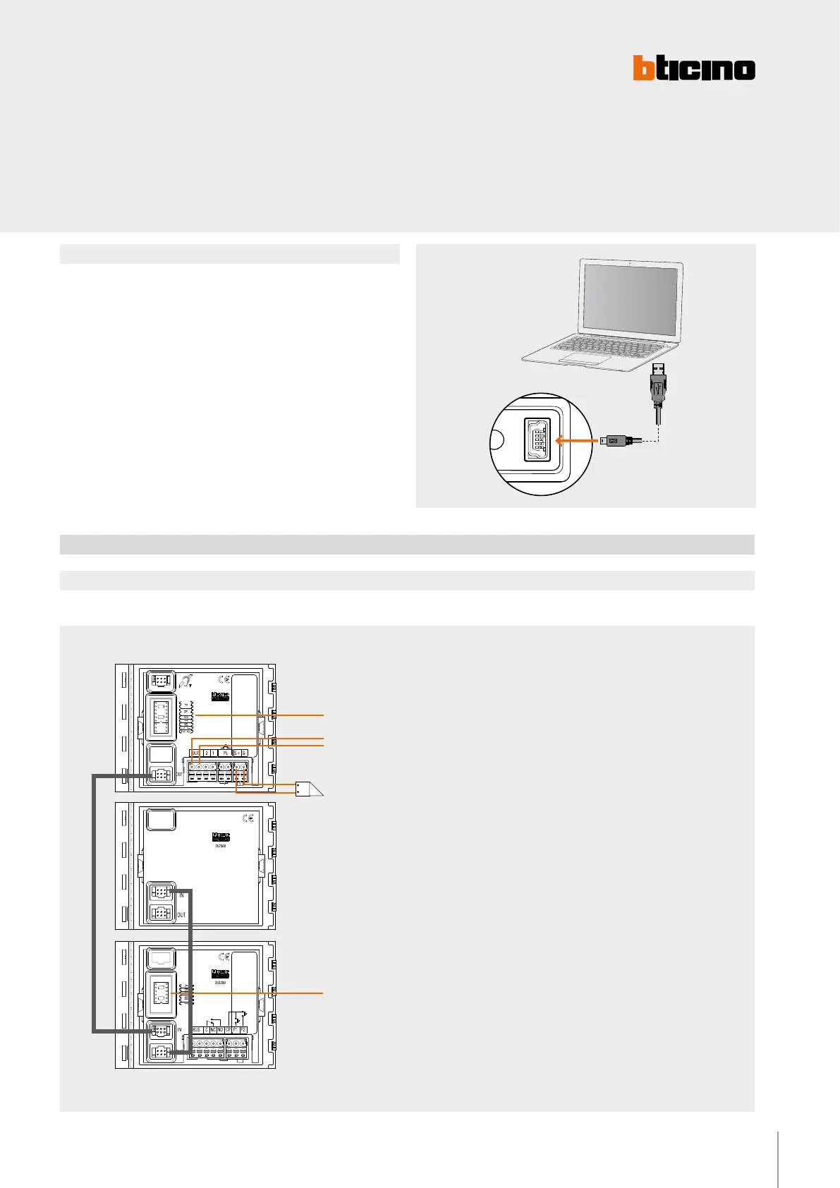
Mode 2 requires advanced configuration of the device, performed using a PC and the
TisferaDesign software (which can be downloaded free of charge from the www.bticino.com
).
For the connection to the PC use a USB - mini USB cable. The software gives the
possibility of configuring, programming, and updating the firmware of the speaker
module. The presence of the mini USB connection of the front of the speaker module
gives the possibility of performing these operations without the need to disassemble
the device.
Mode 2
Wiring diagram
Wiring diagram- Installation with SFERA NEW EP
Example of installation of the RFID module inside a 2 WIRE SFERA NEW pushbutton panel with SCS BUS NOT CONNECTED to the RFID module
Configure as indicated on the
device technical sheet
BUS TK - 2-WIRE SCS
Electrical door lock
18 V 4 A impulsive - 250 mA holding
current 30 Ohm max
Pushbutton
module
A + B + C - DO NOT CONFIGURE
M - DO NOT CONFIGURE
T - DO NOT CONFIGURE
2 WIRE A/V module
WARNING: Irrespective of the position of the SFERA NEW
modules, the RFID module must the FIRST DEVICE connected
to the advanced speaker module or to the audio/video module.
Any other modules (e.g. pushbuttons) must be connected after
the RFID module.
NOTE: the M = 0 configuration (no configurator
connected), only enables management of RESIDENTS badges.
To add and/or delete residents badges, the badge programmed
as MANAGER MASTER badge is required.
 Loading...


