Group 6 Operation – Interfaces Page 57
Release 3.00 Leibinger-Jet 2 se
6.4 Interfaces
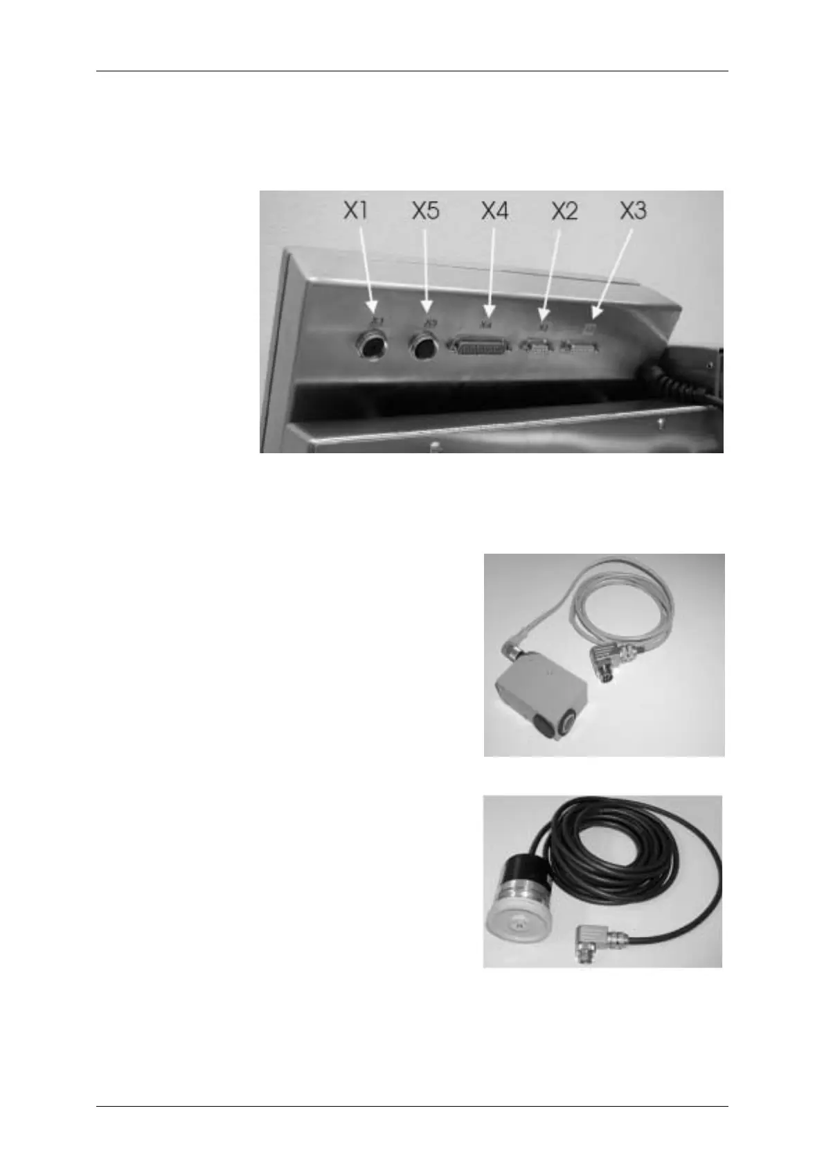
The following interfaces are available on the rear side of the electronics cabinet.
Figure 23
X1 – Shaft encoder
X2 – Data RS 232
X3 – Outputs
X4 – Inputs
X5 – PrintGo
6.4.1 Data interface X2
On the 9-pole SUB-D bush an external PC can be connected for data entry using a
corresponding connection cable.
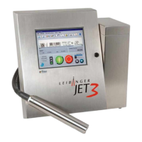
6.4.2 PrintGO interface X5
Figure 24
On the 5-pole diode bush, depending on the PIN
occupation, PNP or NPN product sensor or
potential-free contact can be connected for
triggering the print.
Article no.: see group Replacement parts -
periphery
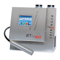
6.4.3 Shaft encoder interface X1
Figure 25
On the 12-pole diode bush a shaft encoder can be
connected for the synchronisation of the product
speed with the print speed.
Article no.: see group Replacement parts –
periphery
Should alternative shaft encoders be used the minimum impulse issue should be 3
impulses/mm in order to achieve an efficient resolution!
Product
Shaft encode