Group 6 Operation – description of the device Page 68
Release 3.00 Leibinger-Jet 2 se
Risk of injury!
Ink escapes from the head aperture. Spraying of ink into the eyes
can cause blindness. Eye protection is necessary!
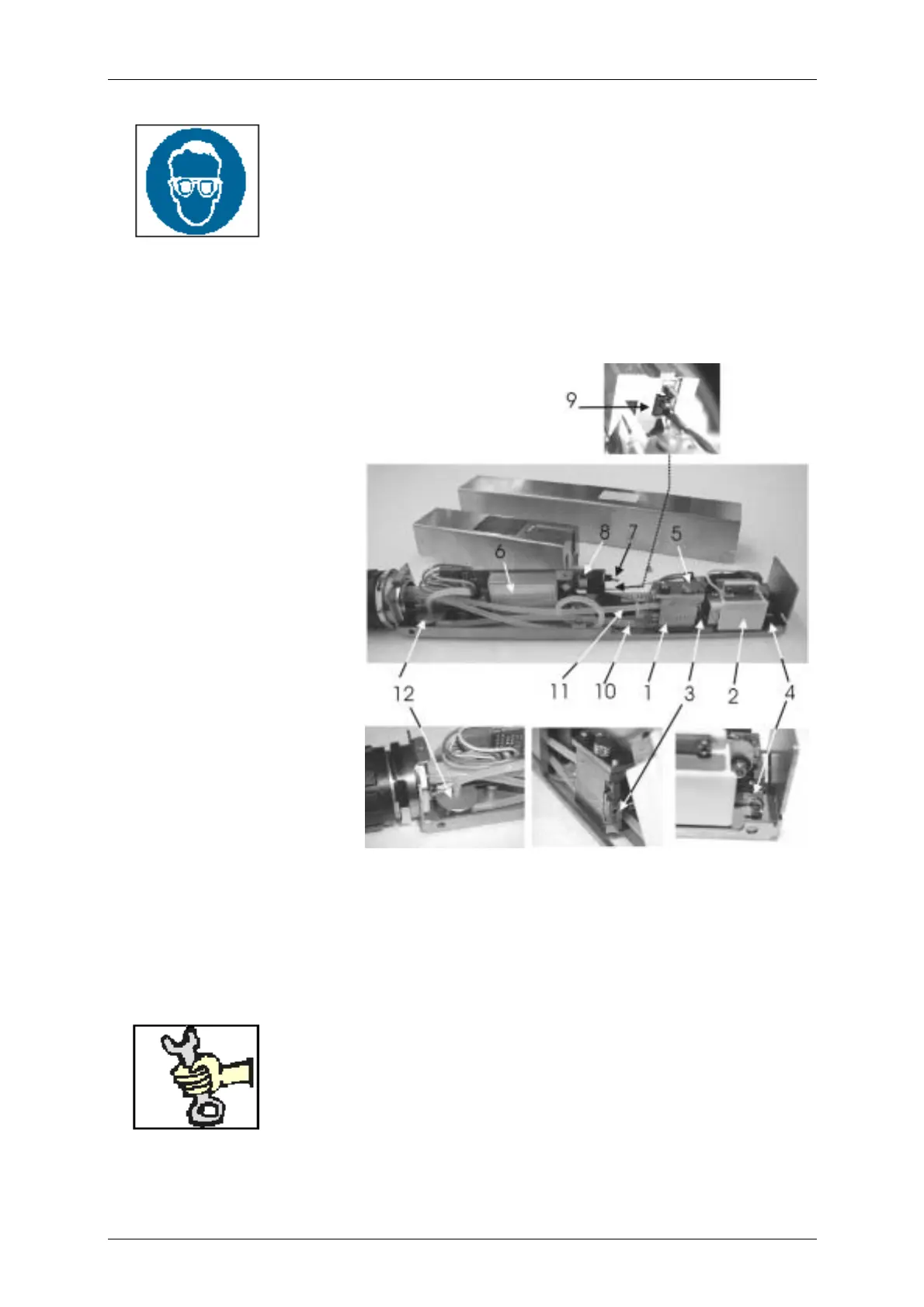
The print head contains all mechanical, electronic and hydraulic components that are
necessary for the creation of an inscription. It is connected to the hydraulics housing via
a flexible tube.
Figure 36
Print head
(without cover)
1 – Drop production unit with oscillator
2 – Deflector unit with deflector plates
and charging electrode
3 – Nozzle plate
4 – Gutter (catcher pipe)
5 – Jet fixing screw with bar
6 – Head electronic
7 – Ink switch
8 – Sensor for switching off the high
voltage with open head cover
9 – Connection for LED (stroboscope)
10 – Ink feed tube
11 – Bleeding tube
12 – Head filter
This work must only be carried out by trained personnel or by
Leibinger service technicians!