Lenze · i700 servo inverter · reference manual · DMS 3.0 EN · 06/2016 · TD06 136
5 Motor control & motor settings
5.12 Fine adjustment des motor model
_ _ _ _ _ _ _ _ _ _ _ _ _ _ _ _ _ _ _ _ _ _ _ _ _ _ _ _ _ _ _ _ _ _ _ _ _ _ _ _ _ _ _ _ _ _ _ _ _ _ _ _ _ _ _ _ _ _ _ _ _ _ _ _
4. Set the characteristic by means of the determined values for Vp (but do not enter any values in
0x2C04
or 0x3404 for axis B yet).
• Here, the values of the grid points which have not been adjusted must be determined by
interpolation between two values.
• Note: In this example it was assumed that the inductance does not change considerably
below 3.75 A. For this reason the same Vp value resulting from a measurement with a motor
current of 3.75 A was used for all grid points below 3.75 A.
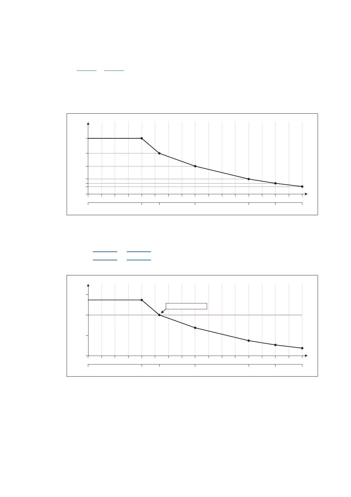
[5-6] Determined saturation characteristic
5. Set the gain Vp and the reset time Tn to the values that have been determined during the
adjustment with rated motor current (in this example "5 A"):
•Set 0x2942:1
(or 0x3142:1 for axis B) = "3.8 V/A".
•Set 0x2942:2
(or 0x3142:2 for axis B) = "5 ms".
6. Scale the Vp values on the Y axis of the characteristic to a Vp setting of "3.8 V/A":
[5-7] Scaling of the determined saturation characteristic to "100 % Vp"
15 A7.5 A3.75 A 11.25 A 12.38 A5A
0 6.25 12.5 18.75 25 31.25 37.5 43.75 50 56.25 62.5 68.75 75 81.25 87.5 93.75 100
Vp [V/A]
0A
0
1.0
1.4
2.6
3.8
5.2
I
max
[%]
x2 x3 x4 x5 x6 x7 x8 x9 x10 x11 x12 x13 x14 x15 x16 x17x1
0.7
15 A7.5 A3.75 A 11.25 A 12.38 A5A
0 6.25 12.5 18.75 25 31.25 37.5 43.75 50 56.25 62.5 68.75 75 81.25 87.5 93.75 100
Vp [%]
0A
0
100
I
max
[%]
x2 x3 x4 x5 x6 x7 x8 x9 x10 x11 x12 x13 x14 x15 x16 x17x1
Vp = "3.8 V/A" 100 %º
50
150