5 Motor control & motor settings
5.12 Fine adjustment des motor model
137
Lenze · i700 servo inverter · reference manual · DMS 3.0 EN · 06/2016 · TD06
_ _ _ _ _ _ _ _ _ _ _ _ _ _ _ _ _ _ _ _ _ _ _ _ _ _ _ _ _ _ _ _ _ _ _ _ _ _ _ _ _ _ _ _ _ _ _ _ _ _ _ _ _ _ _ _ _ _ _ _ _ _ _ _
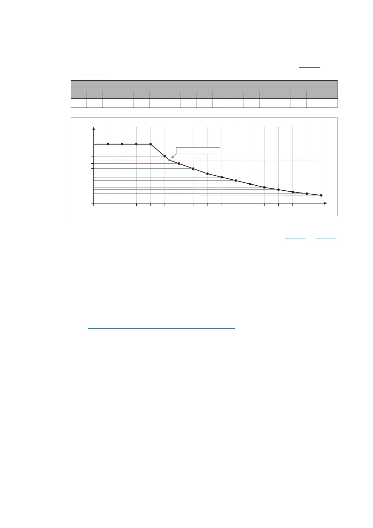
7. Enter the Vp values in per cent from the grid points into the subindices of object 0x2C04
(or
0x3404
for axis B):
[5-8] Grid point values of the saturation characteristic determined
8. Enter the maximum process current ("15 A") as maximum current in object 0x6073 (or 0x6873
for axis B).
• With these settings, the same current characteristic should occur, irrespective of the current
magnitude.
• Since the current controller gain is now corrected actively, the step responses may differ
slightly compared to the previous measurements. In this case, the current controller
parameters must be optimised one last time.
9. For permanent storage: Upload the detected characteristic from the i700 servo inverter into the
Controller.
The »EASY Starter« serves to save the parameter settings of the i700 servo inverter as parameter
file (*.gdc). In the »PLC Designer«, this file can then be imported in the corresponding axis.
Saving changed parameters safe against mains failure
( 53)
Setting for grid points 1 ... 17 in [%]
y1 y2 y3 y4 y5 y6 y7 y8 y9 y10 y11 y12 y13 y14 y15 y16 y17
137 137 137 137 137 109 92 80 68 61 53 45 37 32 26 22 19
0 6.25 12.5 18.75 25 31.25 37.5 43.75 50 56.25 62.5 68.75 75 81.25 87.5 93.75 100
I
max
[%]
Vp [%]
0
109
x2 x3 x4 x5 x6 x7 x8 x9 x10 x11 x12 x13 x14 x15 x16x1
19
137
x17
Vp = "3.8 V/A" 100 %º
92
80
68