Lenze · i700 servo inverter · reference manual · DMS 3.0 EN · 06/2016 · TD06 70
5 Motor control & motor settings
5.4 Manual control
_ _ _ _ _ _ _ _ _ _ _ _ _ _ _ _ _ _ _ _ _ _ _ _ _ _ _ _ _ _ _ _ _ _ _ _ _ _ _ _ _ _ _ _ _ _ _ _ _ _ _ _ _ _ _ _ _ _ _ _ _ _ _ _
Comparison of the test mode "current/frequency" and the "manual control" mode
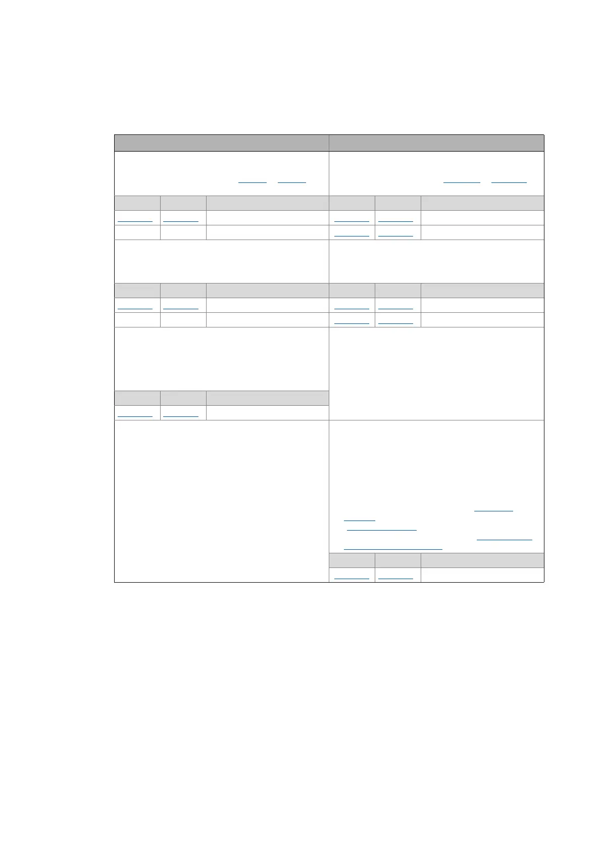
The following table shows the differences between the two modes:
Test mode "Current/frequency" Mode "Manual control"
Current setpoint is pending immediately after controller
enable.
•100% ≡ rated motor current (0x6075
or 0x6875 for
axis B)
Current setpoint is run to the final value via a
parameterisable ramp time after controller enable.
• 100 % ≡ rated axis current (0x2DDF:1 or 0x35DF:1 for
axis B)
Axis A Axis B Parameter Axis A Axis B Parameter
0x2835:1
0x3035:1 Current setpoint 0x2836:1 0x3036:1 Current setpoint (final value)
--(No ramp can be set) 0x2836:3
0x3036:3 Ramp time
Test frequency is pending immediately after controller
enable.
Test frequency is run up to the final value via a
parameterisable ramp time after controller enable (and
is also run down again). The frequency ramp starts when
the current setpoint has reached its final value.
Axis A Axis B Parameter Axis A Axis B Parameter
0x2835:2
0x3035:2 Test frequency 0x2836:2 0x3036:2 Test frequency (final value)
--(No ramp can be set) 0x2836:4
0x3036:4 Ramp time
Starting angle is pending immediately after controller
enable or the rotating field starts with the starting angle.
• In the case of the synchronous motor, a jerky
compensating movement occurs once if the starting
angle does not correspond to the current pole
position of the synchronous motor.
Starting angle is the current commutation angle.
• For the synchronous motor, therefore no
compensating movement should be effected.
Axis A Axis B Parameter
0x2835:3
0x3035:3 Starting angle
Duration unlimited.
(If permitted by the device utilisation and motor
temperature.)
Duration adjustable.
The time starts with the start of the frequency ramp
(when the current setpoint has run up to its final value).
• If the test frequency is not rewritten within the time
set for the time monitoring, the frequency is
decreased to zero via the parameterised ramp.
• When 0 Hz has been reached, the servo inverter
changes to the error status and is inhibited. After the
error has been acknowledged, the "Switch on
disabled" device status has to be changed to the
"Operation enabled
" device status again before
manual control can be continued.Enable/inhibit
operation via control word
Axis A Axis B Parameter
0x2836:5
0x3036:5 Time span for time monitoring