MX32x32DVI-HDCP-Pro and HDMI-Pro
User’s Manual v1.0
Page 41/ 109
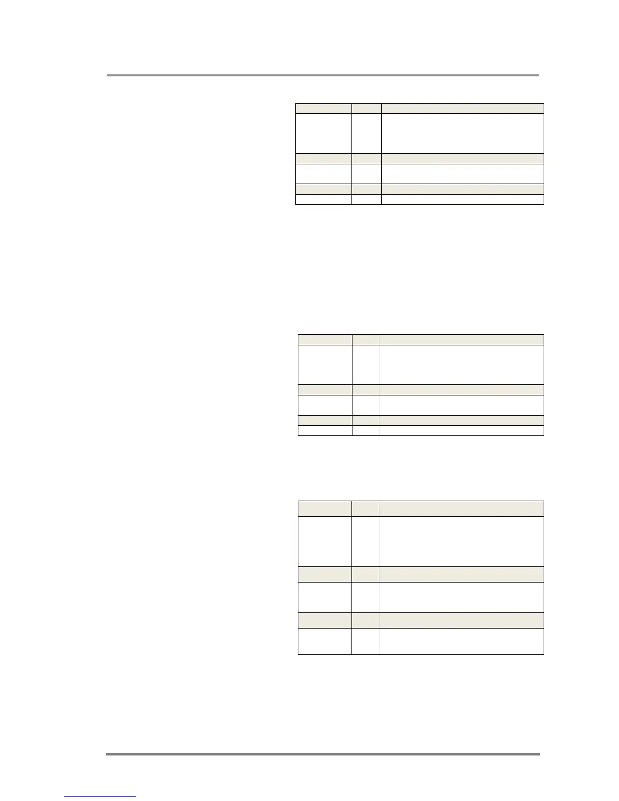
Example 1: View connection on all outputs
Legend 1: output 1 is
connected to input 1,
output 2 is connected
to input 2...output 32 is
connected to input 32,
this is the so-called
„diagonal pattern”.
Info: Note that a space character is sent after the last output
Info: If an output is locked, muted, or both (locked AND muted), the response format
changes. If outputs are muted you get a letter 'M', if locked a letter 'L' and if muted
and locked at the same time 'U' before the 2 digit numbers.
Info: The router will always respond 32 output states regardless of the installed output
cards, as the number of outputs correlates to the frame and not to the number of
installed outputs.
Example 2:
Legend 2:
The connections are
almost the same as in
example 1, but output 1
is muted, output 2 is
locked to input 2 and
output 3 is muted, and
locked to input 3.
4.1.5. View mutes on all outputs
Description: The length
of the response
depends on the number
of outputs installed in
the router. The
response above
presumes a router
having 32 outputs.
Indexes show the actual
output and the number
at the given index
shows its state. If the
value M5 equals 1, it
means that output 5 is
muted, if 0, output 5 is
not muted.
→ {VC}
←
(ALL 01 02 03 04 05 06 07 08
09 10 11 12 13 14 15 16
17 18 19 20 21 22 23 24
25 26 27 28 29 30 31 32 )CrLf
→ {VC}
←
(ALL 01 02 03 04 05 06 07 08
09 10 11 12 13 14 15)CrLf
→ {VC}
← (ALL 01 02 03 04 05 06 07 08)CrLf
→ {VC}
←
(ALL M01 L02 U03 04 05 06 07 08
09 10 11 12 13 14 15 16
17 18 19 20 21 22 23 24
25 26 27 28 29 30 31 32 )CrLf
→ {VC}
←
(ALL M01 L02 U03 04 05 06 07 08
09 10 11 12 13 14 15)CrLf
→ {VC}
← (ALL M01 L02 U03 04 05 06 07 08)CrLf
→ {VM}
←
(MUT●M1●M2●M3●M4●M5●M6●M7●M
8●M9●M10●M11●M12●M13●M14●M15
●M16●M17●M18●M19●M20●M21●M22
●M23●M24●M25●M26●M27●M28●M29
●M30●M31●M32)CrLf
→ {VM}
←
(MUT●M1●M2●M3●M4●M5●M6●M7●M
8●M9●M10●M11●M12●M13●M14●M15
●M16)CrLf
→ {VM}
←
(MUT●M1●M2●M3●M4●M5●M6●M7●M
8)CrLf