Page 105 of 295
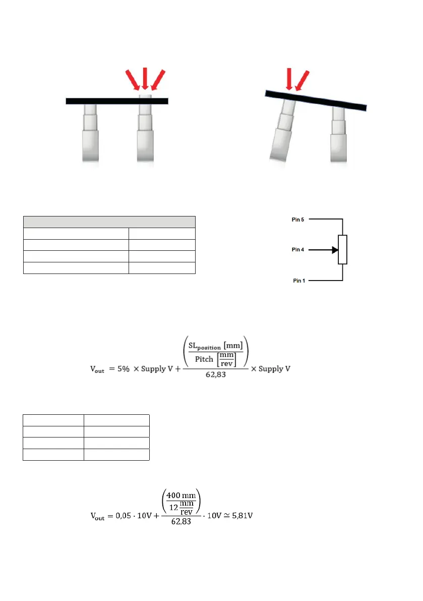
When mounting more than one LC3 you need to consider the fixation:
If you do have a trend/anti-trend function in your application, you
need to mount one or more of the LC3’s with a slider.
Having sliders prevents the column from bending as illustrated below.
The reason why it is important only to fix one column, is that the columns
will not move exactly in parallel – even if you have positioning such as hall.
If more than one column is fixed it can lead to dangerous situations.
Feedback specifications: Potentiometer
Feedback specificationFeedback specification
VCC max. 15 V
Potentiometer total resistance 10 kΩ ± 20%
Non-linearity ±2%
Hysteresis ±2%
Calculation of output vs. SL/pitch
Notice: Only one gearing available for stroke length variants up to 700 mm
The output ratio of a potentiometer for a given position is defined as:
where SL
position
is the actual position in millimeters on the stroke length (SL), relative to end-stop inwards. In that position, the potentiometer output is
5% of full-scale. Spindle pitch is dependent on the variant, whose value can be found in the table below:
Variant Pitch [mm/rev]
4000 N 20
5000 N 16
6000 N 12
Example, in a system connecting a 10 V supply to potentiometer with an SL position of 400 mm and 6000 N variant, the output voltage at the given
position is:
Ordering code no.: 0P