Page 106 of 295
Input/output specifications: dual Hall positioning
Dual Hall digital (F3) with power switch
Item Specification Comment
Pin
configuration
Pin 1 GND
Pin 2 VCC
Pin 3 M+
Pin 4 HALL A
Pin 5 HALL B
Pin 6 M-
VCC 4-15V
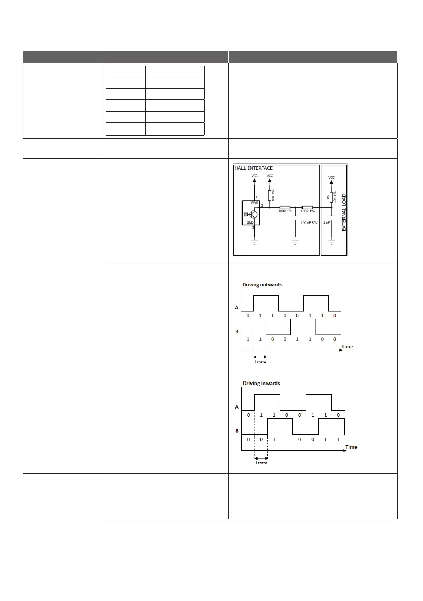
Current Maximum 15 mA @10 kΩ and 1 nF load.
See diagram.
HALL A/B TState is minimum 5ms in all states
(11,10,00,01) at a minimum mechanical load.
Tested with the above specified load.
Duty cycle Hall A 30-70%
Duty cycle Hall B 30-70%
Low level <GND+0.5V @10 kΩ and 1nF load
High level >VCC-0.5V @10 kΩ and 1nF load
Signal pattern during movement:
Resolution Number of dual Hall state shifts/spindle turn:
N = 61.67 state/turn:.
4000 N: 0.324 mm per shift
5000 N: 0.260 mm per shift
6000 N: 0.195 mm per shift
s