Page 45 of 295
Input/ Output specifications: Dual Hall encoded (04 in ordering example)
Item Specification Comment
Description The actuator can be equipped with two hall sensors
A and B and a spindle magnet. In this way you can
have pulses from the actuator when it moves.
Only use for standard actuators, with LINAK A/S
Control Boxes for OpenBus™.
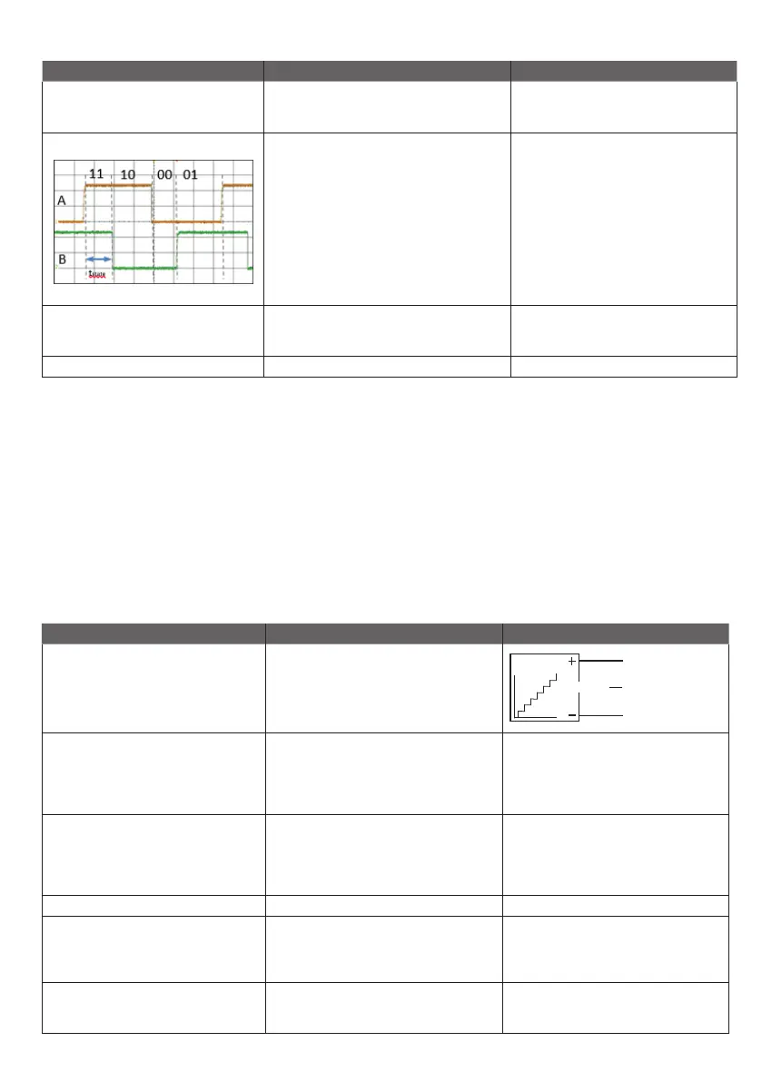
Resolution The feedback system has an 8P magnet which gives
16 shifts in pulses per spindle turn:
3 mm pitch = 0.1875 mm per pulse
5 mm pitch = 0.3125 mm per pulse
6 mm pitch = 0.375 mm per pulse
9 mm pitch = 0.5625 mm per pulse
12 mm pitch = 0.75 mm per pulse
20 mm pitch = 1.25 mm per pulse
See drawing for details.
Tstate is minimum 5ms in all states (11.10.00.01)
Pulse/pause minimum 10 milli-seconds.
On 100 mm stroke you will have the following
number of pulses:
3 mm pitch = 533 pulses
5 mm pitch = 320 pulses
6 mm pitch = 267 pulses
9 mm pitch = 178 pulses
12 mm pitch = 133 pulses
20 mm pitch = 80 pulses
Connection 6 pins mini-fit Use cables:
Standard 6 wires:
0237003-xxxx
Combination Only standard
Input/ Output specifications: Hall Potentiometer feedback (1x and 2x in ordering example).
The Hall Potentiometer feedback is a an option on LA23. This is especially suitable for wheelchairs or TECHLINE applications as the LINAK control boxes
are not capable of handling the signal.
The main advantages are:
• Hall potentiometer is close to being an absolute positioning system
• Hall potentiometer is a long lasting and wear-resistant positioning system
• Enables compact products to have precise positioning (potentiometer increases the product potential)
Input/Output specifications: Hall Potentiometer feedback
Item Specification Comment
Description The actuator can be equipped with an electronic
circuit that gives a feedback signal when the
actuator moves.
Input voltage 10 - 28 V DC
Ripple down to 6 V acceptable
Limit supply to 500 mA or 500 mA
fuse in case of wrong polarisation.
Feedback circuit has to be powered 1 second
before and after the motor runs and until the
actuator has stopped.
Cable dimension 0.5 mm
2
AWG20
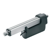
Output voltage 0 - 10 V +/- 0.5 V @ Load > 100kΩ
0 V = Fully retracted
10 V = Fully extended
Can be configured between
0 - 10 V
Example:
1 V = Fully retracted
9 V = Fully extended
Current consumption Current consumption is max. 40 mA @ 12 V Also when actuator is not running.
Connection Supply: White
Ground: Black
Signal: Violet
Use Cables:
PLC/Absolute positioning
8 wires
0237003-xxxx
Combinations The absolute positioning can be combined with
potential free switches.
But cannot be combined with relative positioning.
SIGNALSIGNAL