LS SERIES SERVICE MANUAL
ISSUE 4.0 MICROPROCESSOR CIRCUITS 2
The test data can be output to a Datalogger or to Windows Hyperterminal etc. using a Baud
Rate of 9600 with 8 Data Bits, 1 Stop Bit and No Parity. The FLASH program (embedded) may
be upgraded using a Baud Rate of 57,600 with 8 Data Bits, 1 Stop Bit and No Parity.
The machine can also be operated by a computer using the Lloyd Instruments NEXYGEN
Plus 3 software, which automatically uses a Baud rate of 57,600.
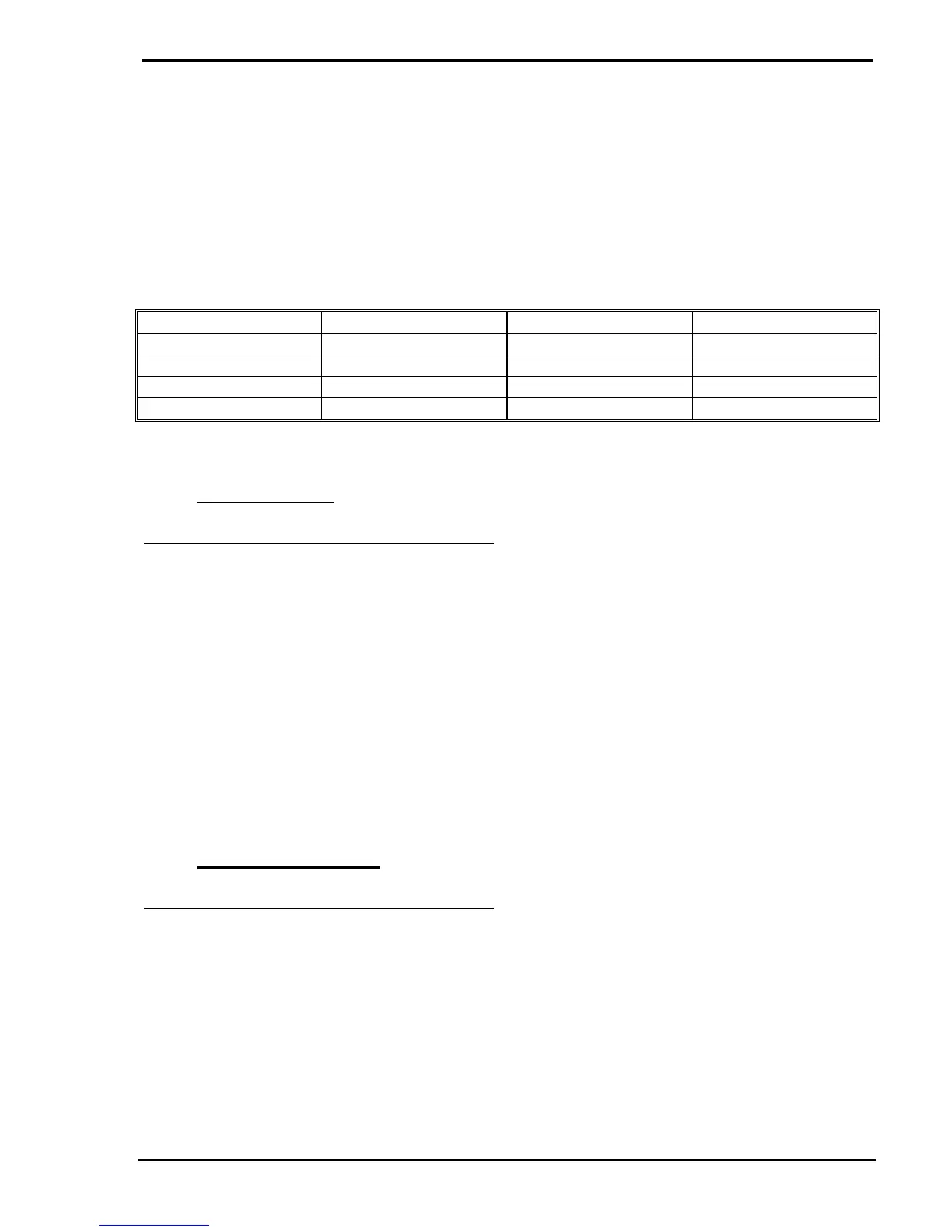
The USB cable is a 4-pin Type A to 4-pin Type B, part number CBT/1357/00 and the pin
numbers are shown below: -
MACHINE COMPUTER WIRE COLOUR FUNCTION
1 1 Red Vcc
2 2 White USB Data -ve
3 3 Green USB Data +ve
4 4 Black Ground
2.3 Console Keypad
See diagram 04/1455 sheet 3 in section 17
The microprocessor is connected to the keypad, LCD display, ADC and the motor control
system via the programmable PLA, IC26.
The full control console or the hand held remote is electrically connected to the 37 way D
connector, P5, on the Main PCB by an external cable.
The membrane keypad for the full control console consists of 25 keys on a 5 by 5 matrix but
the membrane keypad for the hand held remote consists of 9 keys on a 5 by 3 matrix.
Note that the "Soft Keys" under the Full Control Console display are termed A, B, C and D on
the drawing, where A is the left-hand key, B is the next etc.
2.4 Motor Control Signals
See diagram 04/1455 sheet 3 in section 17
The machine is fitted with a PWM Drive system that requires an enable signal and a PWM
signal.
The enable signal (ENABLE) is normally Low and goes High to drive the machine. This
signal is produced on pin 43 of the PLA, IC26, and is fed to the Motor Drive PCB via pin 13 of
the 26-way ribbon cable.
The PWM signal (PWM) is produced on pin 52 of the PLA, IC26, and is fed to the Motor Drive
PCB via pin 10 of the 26-way ribbon cable. Note that a decreasing pulse width drives the
machine upwards and an increasing pulse width drives the machine downwards.