LS SERIES SERVICE MANUAL
ISSUE 4.0 MICROPROCESSOR CIRCUITS 5
2.6 Splinter Shield Wiring
If the machine is NOT fitted with a splinter shield, then a link will be fitted across pins 1 and 2
of the 3-way Molex header, CN5.
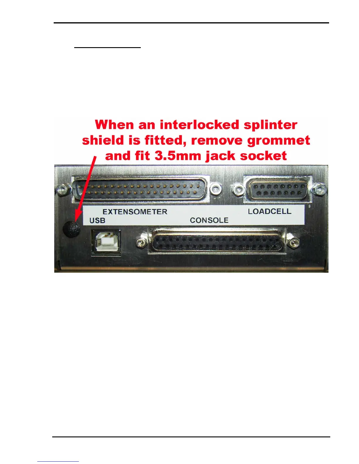
If an optional interlocked splinter shield is fitted, the link across pins 1 and 2 of the 3-way
Molex header, CN5, is removed and an internal splinter shield loom, part number 09/1046, is
connected to CN5. This loom has a 3.5mm jack socket fitted to the other end and this socket
is mounted onto the rear panel in place of the blanking grommet.
The interlocked splinter shield is fitted with a normally open (N/O) switch and this is open
when the shield is open and closed when the shield is closed.
One side of the shield switch is connected to pin 1 of CN5 on the Motor Drive PCB and this is
connected to pin 38 (Guard) of the PLA, IC26, via pin 18 of the 26-way ribbon cable. The
other side of the shield switch is connected to pin 2 of CN5 on the Motor Drive PCB and this
is connected to 0V. The "Guard" line can be pulled high by a resistor in NR11 but is pulled
low when the splinter shield is closed.
If a test is started, or the Return key is pressed, when the splinter shield is open, a "Splinter
Shield Open" error message will be displayed on the console.
Note that the embedded will allow the jog keys to drive the machine when the splinter shield
is open. This is to allow the user to position the crosshead when fitting a sample.