LS SERIES SERVICE MANUAL
ISSUE 4.0 DIAGNOSTIC MODES 3
Each /E Series Extensometer is fitted with an extensometer plug which contains an 04/1408
extensometer amplifier/connector PCB. These extensometers are supplied ready for use with the
bit scale already defined.
Other series of extensometers may be converted by using an adapter kit 07/2053/S, which consists
of an 04/1408 extensometer PCB and a metal 25 way D housing. A converted Analogue
Extensometer will require the amplifier gain and bit scale to be set and a converted Digital
Extensometer will require the bit scale to be set.
11.5 Converting an Analogue Extensometer
To connect a self powered 10V full scale extensometer to the machine (e.g. LASERSCAN or
EXL750), connect the extensometer output from the RING of the output socket to T1 on the
04/1408 extensometer PCB and the extensometer ground to T2. The amplifier IC1 on the
extensometer PCB is set to a gain of 1 by fitting links LK1 and LK2 on the PCB and the amplifier
IC2 is set to a gain of 0.8 by fitting a 12K resistor for R8.
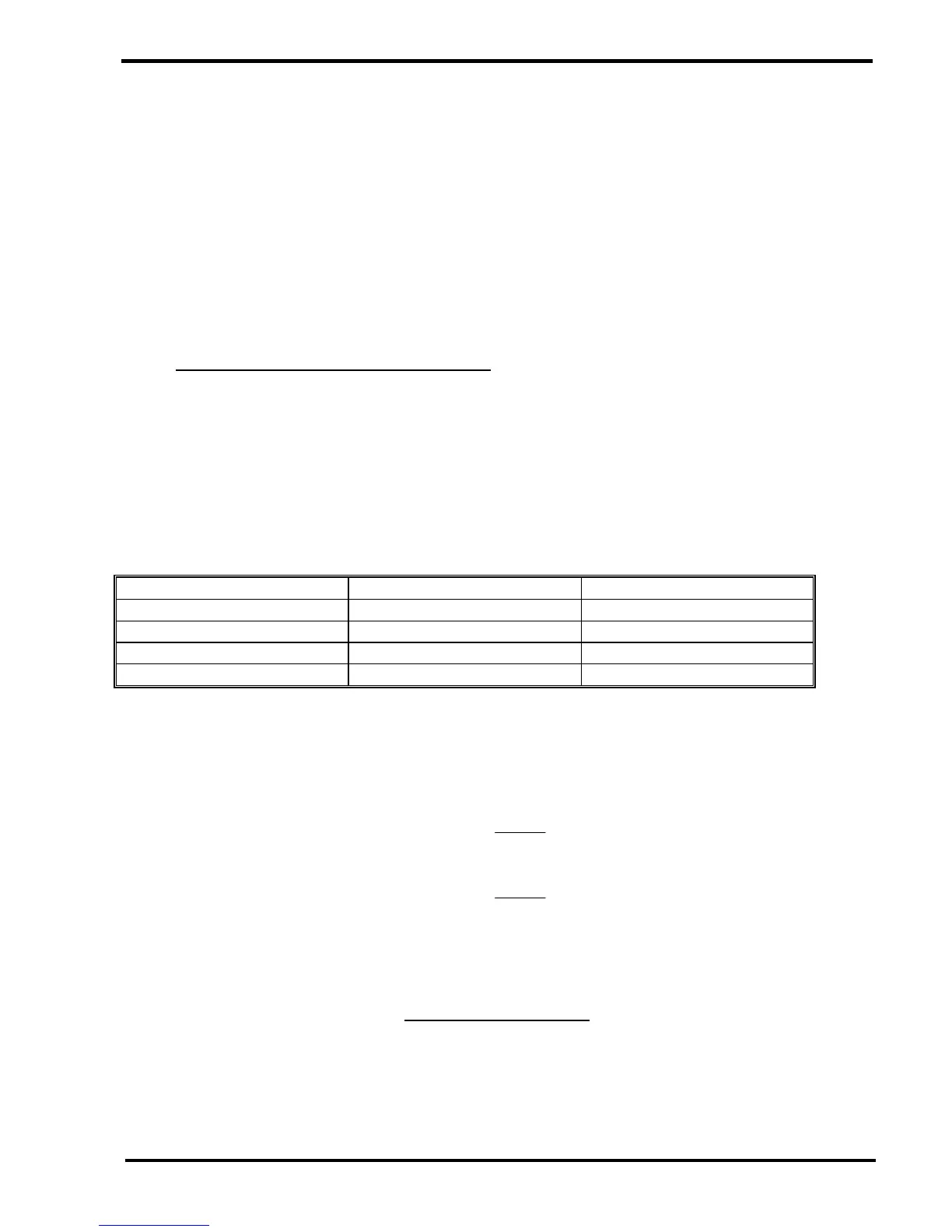
To connect a strain gauge extensometer to the machine (e.g. STGA Series), connect the 4 wires
to the 04/1408 extensometer PCB as shown below:-
STGA WIRE COLOUR 04/1408 TERMINAL 04/1408 FUNCTION
YELLOW T1 INPUT (-)
GREEN T2 INPUT (+)
BLUE T3 EXCITATION (-)
RED T4 EXCITATION (+)
If the extensometer has a sensitivity of 2mV/V or less, remove links LK1 and LK2 to give an
amplifier gain of 1000. If the extensometer has a gain of more than 2mV/V, fit link1 but remove
LK2 to give an amplifier gain of 100. The amplifier IC2 is set to the required gain by selecting a
suitable value for resistor R8 using the formulas below: -
Amplifier gain set to 1000 R8 =
VmV /
30
K Ohms
Amplifier gain set to 100 R8 =
VmV /
300
K Ohms
Calculate the extensometer bit scale using the formula below: -
Extension Range (mm)
26215
Note that the signal from an Analogue External Extensometer is converted into data using a 16 Bit
ADC.