LS SERIES SERVICE MANUAL
ISSUE 4.0 CROSSHEAD DRIVE 2
The High on IC5B pin 4 is also inverted by IC5D and the Low output on pin 11 switches off the
Drive LED (DS3) and also switches off Q3 to provide a FAULT signal. This signal is fed to the
Main PCB where it reaches the microprocessor via IC26 pin 39.
When the machine is to run, the ENABLE signal will go High, the collector of Q6 will be pulled
High by R16, the DISABLE signal will go Low to enable the PWM Driver IC and the Drive LED
(DS3) will light.
Note that the pull-up resistor R16 is fed from the +12V Reference supply so the fault line will be
activated if this +12V supply fails. The +12V Reference supply is produced from the high
current motor supply, so if this supply fails (blown fuse etc) then the fault line will be activated.
The PWM signal is provided by IC26 pin 52 on the Main PCB and is fed to IC1 pin 2 on the
Motor Drive PCB.
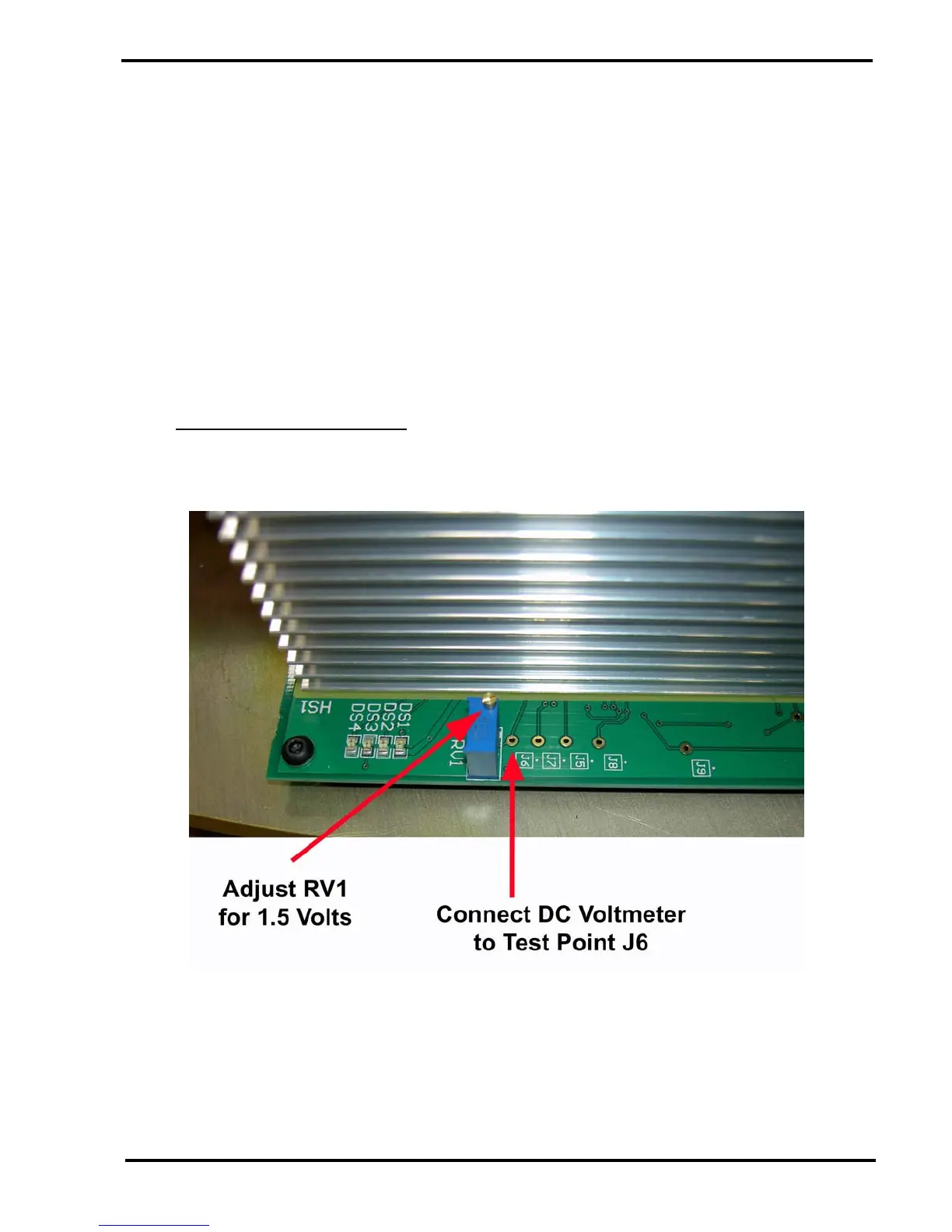
7.3 Motor Overcurrent Detector
The Motor Drive PCB is set to current limit at 15 Amps. This is set by the potential from RV1
(1V5) and is measured and adjusted as shown below: -
When the machine is running, the motor current will pass through either R10 or R11. The motor
current will develop a voltage across R11 when the motor is driving upwards and this voltage is
fed to the comparator IC4A. The comparator has its –ve input held at the "Trip" voltage (+1.5V
set by RV1) so if the voltage across R11 exceeds this voltage, the comparator output will go
High and set the latch IC3A. The Q output of the latch will go High and light the Tension
Overcurrent LED (DS2) to indicate that the motor circuit has tripped.