LS SERIES SERVICE MANUAL
ISSUE 4.0 CROSSHEAD DRIVE 4
The +12V is also fed to the base of Q2 and the low on Q2 collector feeds a "Safe Line Open"
signal (SLOPEN) to pin 34 of the microprocessor IC26 on the Main PCB. The Motor Drive
transformer is isolated from the Motor Drive Power Supply because K1 terminals 1 and 3 are
open circuit.
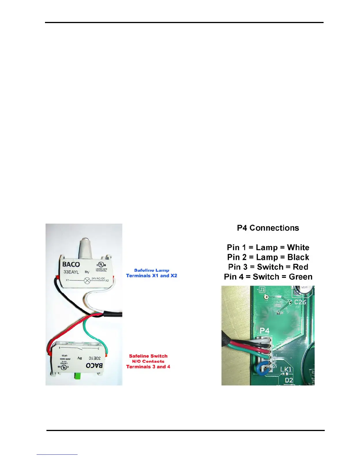
The safeline switch is connected to P4 pins 3 and 4. Pin 4 is connected to +12V and pin 3 is
connected to terminal 6 (N/0-1) of the relay K1 and to terminal 8 (coil) of the relay K1 via the
wire link fitted across P4 pins 5 and 6. When the yellow button is pressed, the +12V on P4 pin 4
is connected to P4 pin 6 so the relay K1 is energised.
When relay K1 energises, the +12V is removed from P4 pin 2 so the yellow safeline lamp is
switched off. Transistor Q2 switches off and the high on Q2 collector feeds a "Safe Line Open"
signal (SLOPEN) to pin 34 of the microprocessor IC26 on the Main PCB. The +12V supply fed
to K1 terminal 4 (common-1) is connected to terminal 6 by the N/O contact. This +12V is fed to
P4 pins 5 and 6 so the relay stays energised when the safeline switch is released. This is the
"hold on circuit". The Motor Drive transformer is now connected to the Motor Drive Power
Supply because K1 terminals 1 and 3 are closed.
The other end of the relay coil is connected to 0V via the transistor Q1. Therefore, the safeline
relay can only be energised if Q1 is switched on. The base of Q1 is fed with the Safe Line
Enable signal (SLEN) and this is produced on pin 53 of the PLA IC26 on the Main PCB. This
signal is normally High but will go low during a software reset (watchdog operates) or when
performing a flash upgrade