LS SERIES SERVICE MANUAL
ISSUE 4.0 MECHANICAL ASSEMBLIES 10
Drive the crosshead close to the top of the machine to help distribute the weight when the machine
is laid over onto its back for dismantling.
Remove the lower cover and the top cap. Also remove the vertical motor cover on an LS2K5E or
LS5S machine.
Disconnect the encoder plug from connector P2 on the Main PCB then unscrew and disconnect
the motor wires from connector P6 on the Motor Drive PCB.
Disconnect the limit switch plug from connector CN2 on the Motor Drive PCB.
Remove all plugs and cables from the rear connectors.
Lay the machine over onto its back and support the top and bottom ends of the vertical column
using 2 wooden blocks. A suitable thickness for each block is 150mm (6 inches). Ensure that the
weight of the machine is NOT applied to any of the rear connectors.
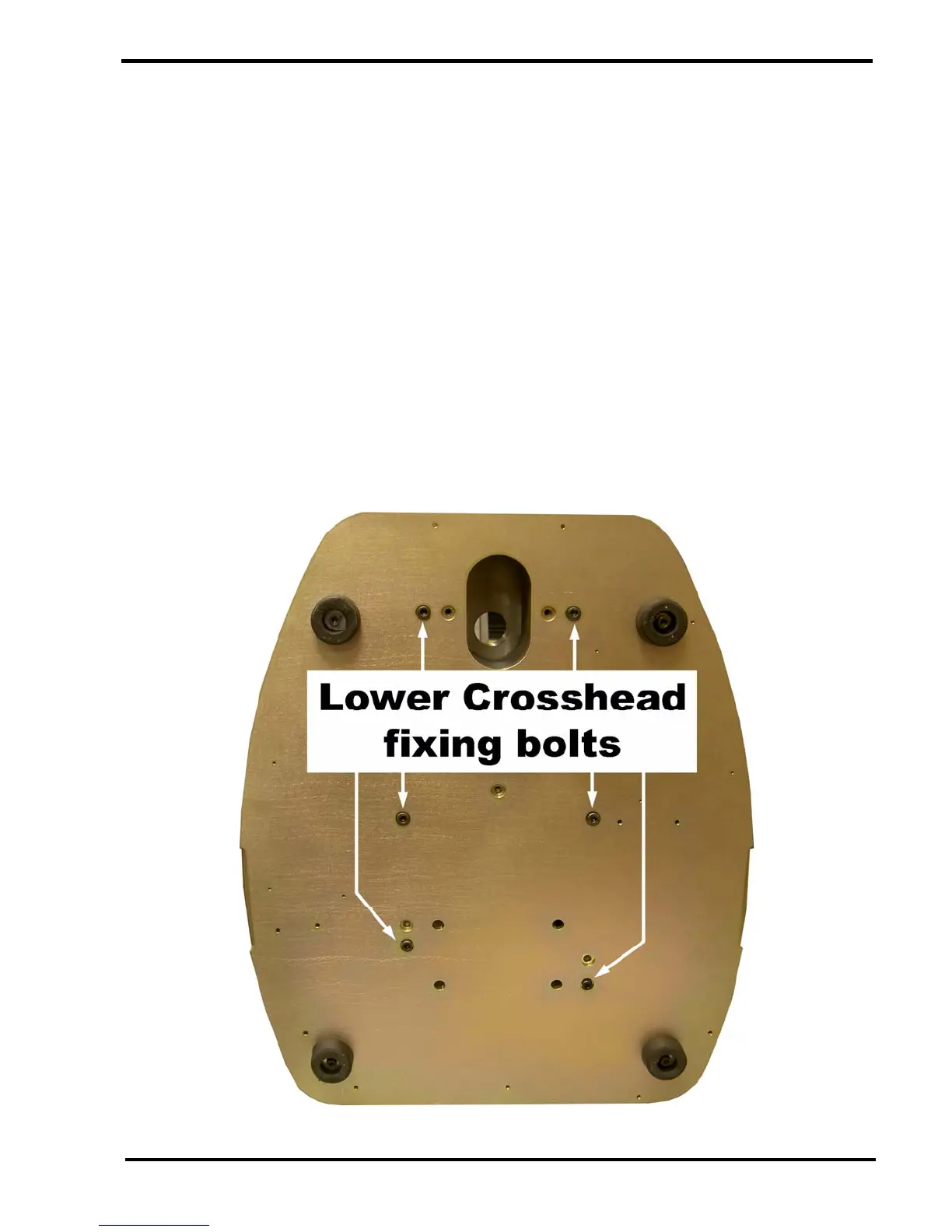
Support the base plate, remove the 6 off 6mm socket head screws that secure the mechanical
assembly to the base plate then lift the base plate clear of the mechanical assembly.