Maintenance 73
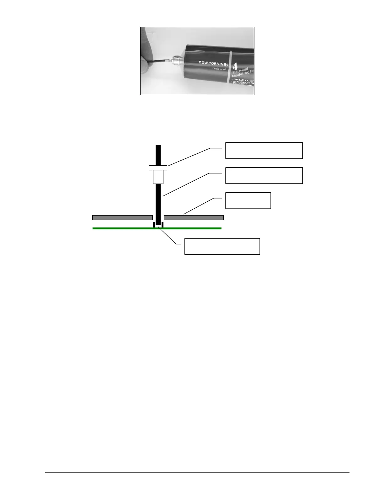
9. Hold the new antenna by the black plastic sheathing and guide it through the hole in the sensor
box. Carefully seat the antenna in its mating connector. When the antenna is correctly seated,
pulling on it will be met with light resistance.
10. Carefully re-thread, screw-in and tighten the white nylon hex bolt to secure the antenna in
place.
11. Reinstall the sensor if necessary (if removed from the boom or jib, an angle sensor will require
re-calibration during the installation procedure, see the angle sensor installation section of the
user manual).
12. Verify that the sensor functions properly.
Load Cells
W
ARNING
! Heavy shock may affect load indication accuracy. Inspect the load cell regu-
larly for clearly visible dents or scratches. Test the load indication if collision damage is
visible.
Reading Accuracy
LSI flat bar load links are pre-calibrated at the factory. No “zeroing” or other calibration is required
on installation. Each link is heat treated to age the steel and ensure stable readings for many
years; the load cells are individually temperature compensated to guarantee accuracy. LSI flat bar
load links are calibrated to indicate between 100% and 104% of their Safe Working Load (SWL).
LSI load pins, line riders and compression cells must be calibrated at installation and every time
thereafter the installation, the load sensor or the transmitter is changed.
White nylon hex bolt
TA011 Antenna
Sensor box
Antenna receptacle
Figure: Seating the antenna
Picture: Coating the antenna foot
SkyAzúl, Equipment Solutions
 Loading...


