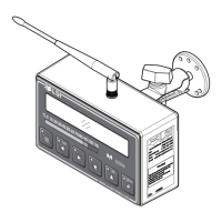
8 The GS550 System
Liquid Crystal Display
Detailed lift data and system information is displayed here. The liquid crystal display (LCD) can be
adjusted to facilitate viewing in varied lighting conditions. See the Display Settings section of this
manual.
Sensor Status Lights
Detailed lift data and system information is displayed here. The liquid crystal display (LCD) can be
adjusted to facilitate viewing in varied lighting conditions.
2 Block. The red 2 Block alarm light comes on when a programmed anti-two-block switch
is in alarm.
The green “M” (main) and “A” (auxiliary) anti-two-block radio status lights stay on when the
GS550 has a reliable radio communication link to all programmed anti-two-block sensors.
The radio status lights flash green when communication is intermittent or absent. The M re-
fers to the first anti-two-block sensor programmed in the sensor list. The A refers to all other
anti-two-block sensors programmed in the sensor list.
Load. The red Load alarm light comes on when a load sensor is in overload.
The green “M” (main) and “A” (auxiliary) load radio status green lights stay on when the
GS550 has a reliable radio communication link to all programmed sensors. The radio status
lights flash green when communication is intermittent or absent. The M refers to the first
sensor programmed in the sensor list except anti-two-block. The A refers to all other sen-
sors programmed in the sensor list except anti-two-block.
Low Battery. The amber light of the battery icon comes on when battery life for a sensor
programmed in the sensor list drops below 10%. Normally several weeks of battery life re-
mains from the moment the low battery light first comes on.
Bar Graph. The bar graph displays the gross load lifted by a load sensor as a proportion of
the maximum load allowed, expressed in 10% increments. Maximum load is the lowest of
the operator set maximum load limit and the working load limit (WLL) as calculated from the
rated capacity charts*. When there are two or more load sensors programmed in the sensor
list the bar graph will indicate the load for the sensor closest to its maximum allowable.
Infrared Port
The infrared port is used to download data from the data logger or to upload firmware updates and
capacity charts using a GT103 portable download tool or other compatible device.
Keypad
The keypad consists of six buttons used to control, consult, program, and troubleshoot the GS550
display and system. Each button has two functions; a primary function for the operation display,
and a secondary function for menu navigation and programming. The secondary functions are
described in the Menu Navigation sub-section of this manual. The primary functions are described
below.
*
WLL is indicated by rated capacity indicators only.
SkyAzúl, Equipment Solutions

 Loading...