54 The GS550 System
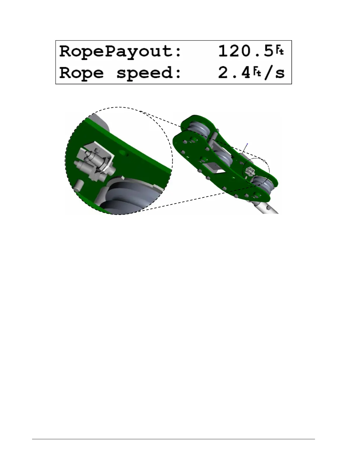
Rope Payout
Typically the rope payout sensor is factory installed on the line rider load sensor. Alternatively the
rope payout sensor may be installed on an appropriate sheave. Power supply must be provided to
the rope payout sensor. A GS550 display can then be programmed to communicate with the
sensor and to indicate rope payout (length) and rope speed.
Rope Payout Calibration Procedure № 1: Mechanical Set-Up
1. Hoist up to reel in the wire rope fully.
2. Install the rope payout system.
3. Verify that the rope payout sensor is programmed in the sensor list (menu 4A1).
4. Zero the rope payout length in the Tare menu (see Operation, Display GS550, Keypad, Tare in
this manual).
5. Hoist down to pay out a known length of wire rope (for example: 20 feet).
6. Verify the rope payout indicated matches the actual length of wire rope paid out. If not then
follow Rope Payout Calibration Procedure № 2.
Rope Payout Calibration Procedure № 2: Correct with the GS550
If rope payout indicated does not match actual rope payout, and if it is not possible to easily correct
by following Rope Payout Calibration Procedure № 1, then follow this procedure. This procedure
requires hoisting up to fully reel in the wire rope, and then hoisting down to pay out a known length
of wire rope. For accurate calibration the “known length” paid out must be accurately measured.
1. Press Menu → Next → Next → Next → to go to menu 4) Installation.
Figure: Rope payout on a line ride
Figure: Rope payout displa
SkyAzúl, Equipment Solutions