Installation 47
Wireless Load Pins
W
ARNING
! Do not pull on a load pin by the pigtail.
LP011, LP015, and LP026
1. Mount the load pin to the boom tip or
block by replacing the pin of the wedge
socket. The load pin is directional and
must be oriented correctly to indicate
load accurately. Install the pin so that the
bracket embraces the wedge socket and
prevents pin rotation.
Tip: When installed at the boom tip the lot
number can be read right side up and the
“line pull” arrow points down towards the
block. When installed at a single part block
the lot number can be read upside down and
the “line pull” arrow points up towards the
boom tip.
2. Secure the load pin in place with a cotter
pin or other suitable keeper device.
Load Pin Transmitter GS001
1. Determine the transmitter mounting position.
a. The load pin and transmitter pigtails must connect easily without stretching or kinking at
all boom angles and working conditions. The jumper cable may be used between the
load pin and transmitter to increase transmitter placement options.
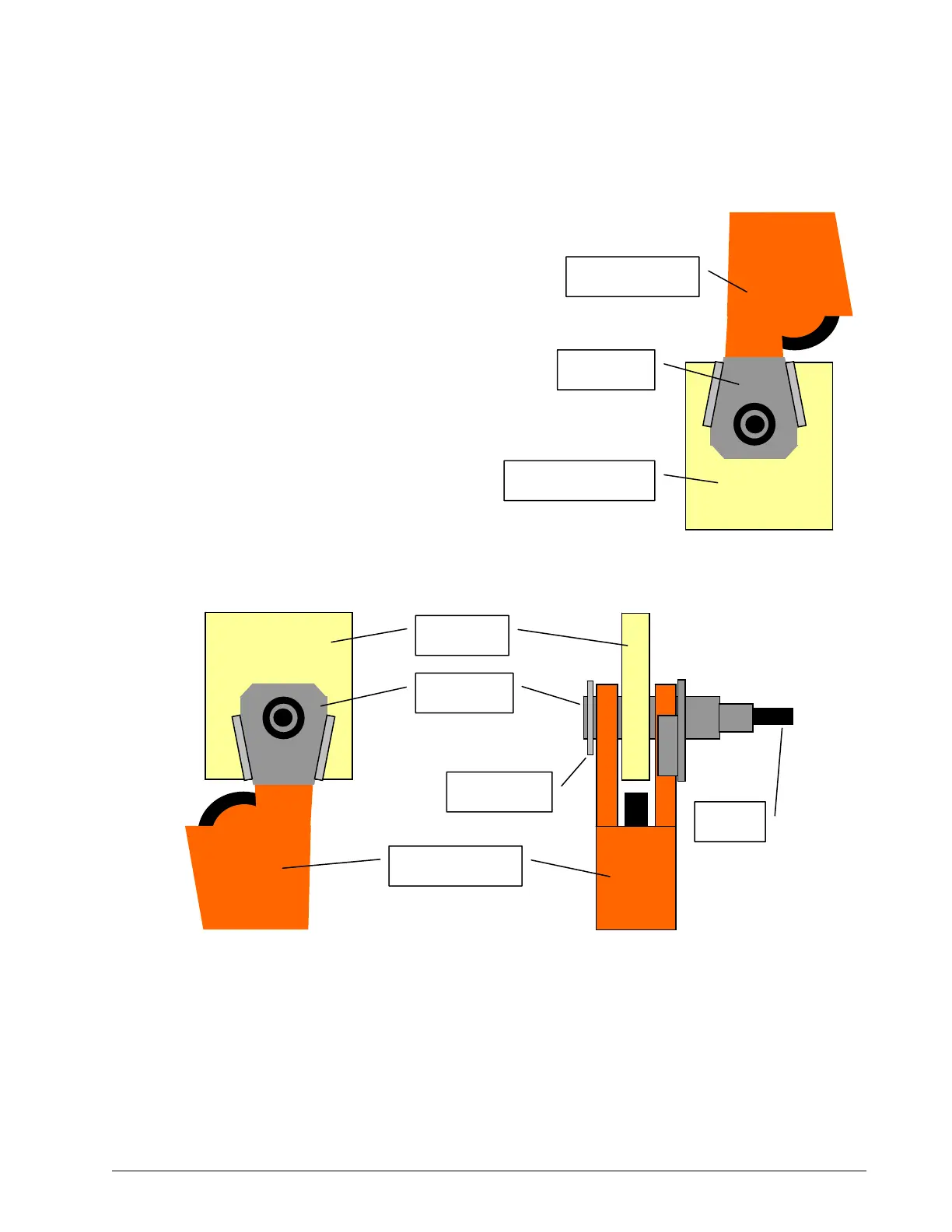
AA10K11
LINE PULL
Load pin
Cotter pin
Wedge socket
Boom tip
Pigtail
Figure: Load pin LP011, LP015, or LP026 – installation at boom tip
↑
Load pin
Single part block
Figure: Load pin LP011, LP015, or LP026 –
installation on a single part block
Wedge socket
SkyAzúl, Equipment Solutions