Installation 23
5. Lockout number 3 (if required): the orange wire functions in the same way as the white and
green wires; see above.
6. Optional Lockout number 4: if purchased with the fourth lockout option, the blue wire will
function in the same way as the white and green wires, see above.
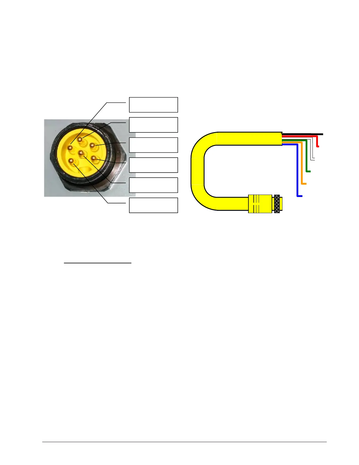
7. Connect the yellow cable to the GS550. The connector is waterproof and well rated for external
environments. Simply connect the cable to the display and gently tighten the nut. Do not put a
kink in the yellow cable where it enters the connector; any bend in the cable at the base of the
connector must not be so severe as to break the internal connections where the cable meets
the connector.
Table: Power and Lockout Connection
Wire Colour Function
Black Negative (ground)
Red Positive 12 or 24 volts (crane power supply)
White Lockout № 1
Green Lockout № 2
Orange Lockout № 3
Blue Optional 4
th
lockout or digital input
Lockout Settings
Warning, alarm and lockout control is programmed in this menu. The GS550 can be programmed
to generate alarms and lockout for almost all programmed limits, and two-block. Furthermore,
warnings are generated when approaching programmed load limits and rated capacity (when
applicable).
Warning level. When gross load (regardless of tare value) approaches the maximum limit
for a load sensor the red overload alarm light will flash. The maximum limit for a load sensor
is lower of the operator set limit (Limit Menu) or the WLL if rated capacity indication is used.
The proportion of a limit that must be reached to trigger the overload warning is the warning
level. The default factory setting for the warning level is 90%.
1. Press Menu → Next → Next → Next → Enter → Next → Next → Next→ Next →
Next → Next → Enter to access menu 4G1) Warning level.
2. Use Up and Down to adjust the warning level.
Blue wire
White wire
Red wire
Green wire
Orange wire
Black wire
Figure: GS550 power supply connector
Figure:
ower supply cable,
art
LB00
SkyAzúl, Equipment Solutions

 Loading...


