Installation 31
8. Press Enter → Next to go to the trim adjustment page.
9. Use Up and Down to adjust the trim value.
Example:
If angle indicated is 0.3° over the actual angle, adjust the trim value to -0.3.
Example:
If angle indicated is 0.9° below the actual angle, adjust the trim value to 0.9.
10. Press Enter to save changes.
11. Press Exit four times to return to the operation display.
12. Verify accurate angle indication at both very high and very low angles.
Anti-Two-Block Switch GS050
W
ARNING
! Keep the anti-two-block switch away from the boom and any connecting
metal structures when welding mounting brackets to the boom. Proximity to welding
may cause permanent damage to the anti-two-block switch and render the anti-two-
block system unsafe.
Important! To ensure reliable radio communication between the anti-two-block switch
and the GS550 display the following conditions must be respected:
• The antenna of the anti-two-block switch must not be in contact with metal.
• The anti-two-block switch antenna must point to the left or to the right of the
boom; it must not point directly to, or away from, the GS550 display.
• The anti-two-block switch antenna must have a clear line of sight to the GS550
display; in most cases this means mounting the sensor on the same side of the
boom as the operator's cab
4B2A) No. x id: Gxxxxx
Load sensor
Heartbeat 60
Up/Down, Enter->Save
Trim: 0.0
Up/Down, Enter->Save
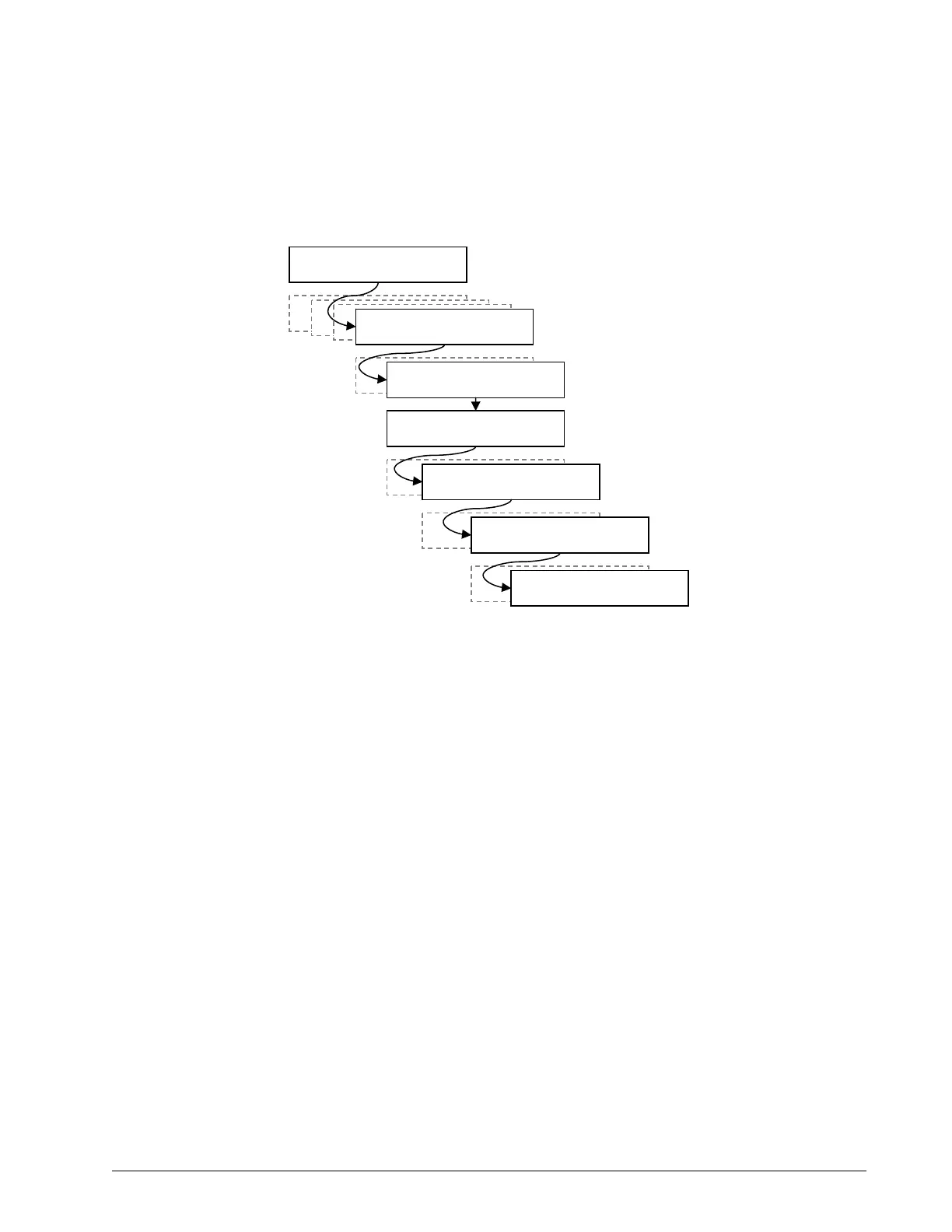
4A) Sensor List
1) Parts of Line
Operation Display
2) Crane Rigging
3) Display Settings
4) Installation
4B) Sensor Calibration
Enter user password:
aaa
4B1) Automatic value
calibration wizard
4B2) Manual parameter
calibration
4B2A) No. x id: Gxxxxx
Angle sensor
Figure: Angle Calibration Procedure
SkyAzúl, Equipment Solutions