Installation 29
Angle Sensors for the Boom or Jib
W
ARNING
! Keep the angle sensor away from the boom and any connecting metal struc-
tures when welding the metal lugs to the boom. Proximity to welding may cause
permanent damage to the angle sensor and prevent accurate angle indication.
Mounting Procedure
The GS010 series angle sensors can be turned on by starting up the GS550 display to which they
are programmed. The angle sensor can then assist in levelling itself with the red and green LED.
1. Determine the angle sensor position.
a. The GS010-01 boom angle sensor can be mounted on either side of the boom.
b. The GS010-02 360° angle sensor must be mounted on the left side of the jib.
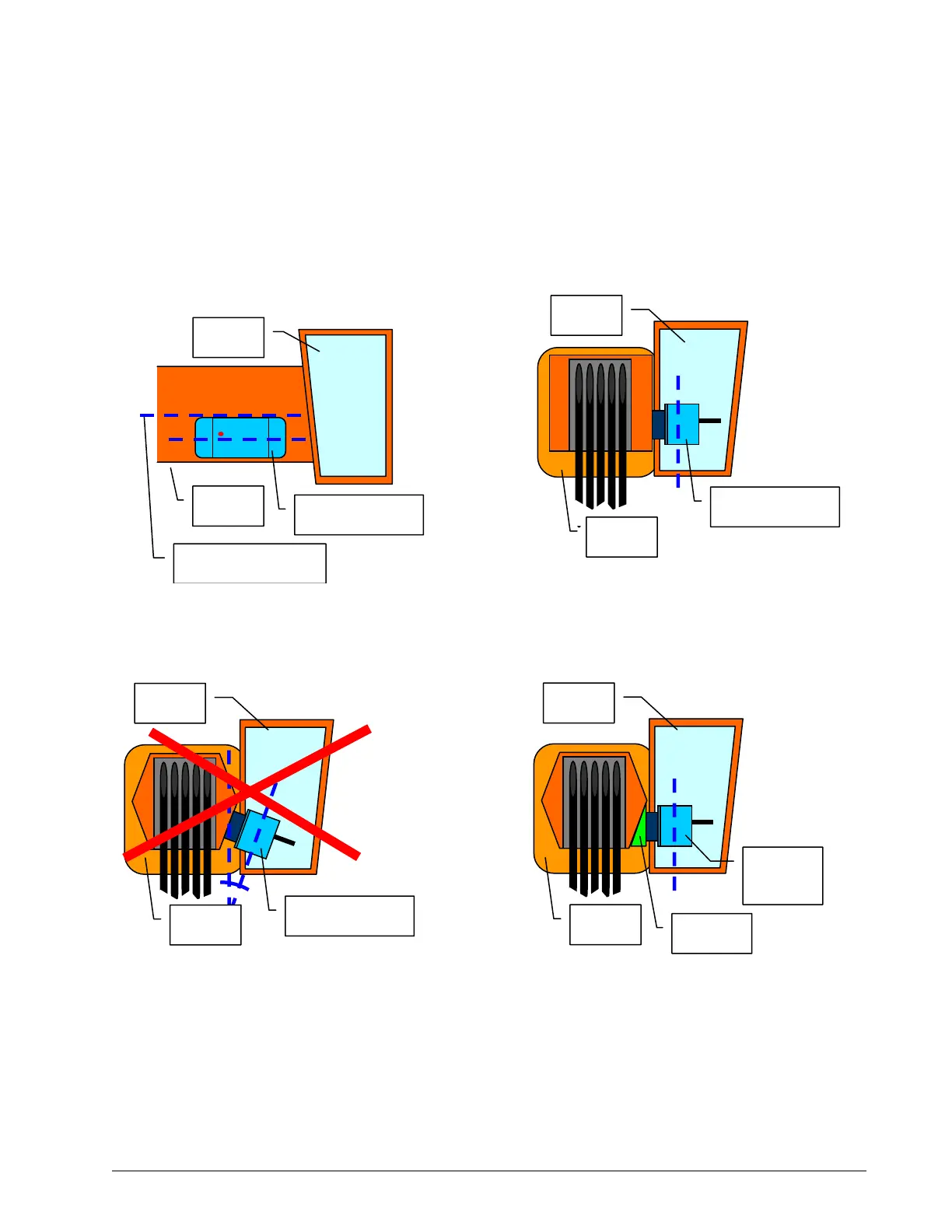
c. The angle sensor must be level with the boom centreline.
d. The top / bottom axis of the angle sensor must be within 15 degrees of vertical
Figure: A wedge used to mount the
angle sensor with its top/bottom axis
within 15° of vertical – front view
Boom
Wedge
Cabin
Angle
sensor
Figure: Do not mount the angle
sensor with its top/bottom axis more
than 15° from vertical – front view
Boom
Angle sensor
Cabin
Figure: Angle sensor
top/bottom axis within 15°
of vertical – front view
Boom
Angle sensor
Cabin
Boom centreline
Boom
Angle sensor
Cabin
Figure: Angle sensor level with
the boom – side view
SkyAzúl, Equipment Solutions