Installation 21
Tip: If the nuts are on the outside of the cab, caulk with silicone between the washers and the cab
to prevent water entry.
4. Loosen the wing nut of the bracket arm to adjust display orientation to facilitate viewing by the
operator and then tighten it back up.
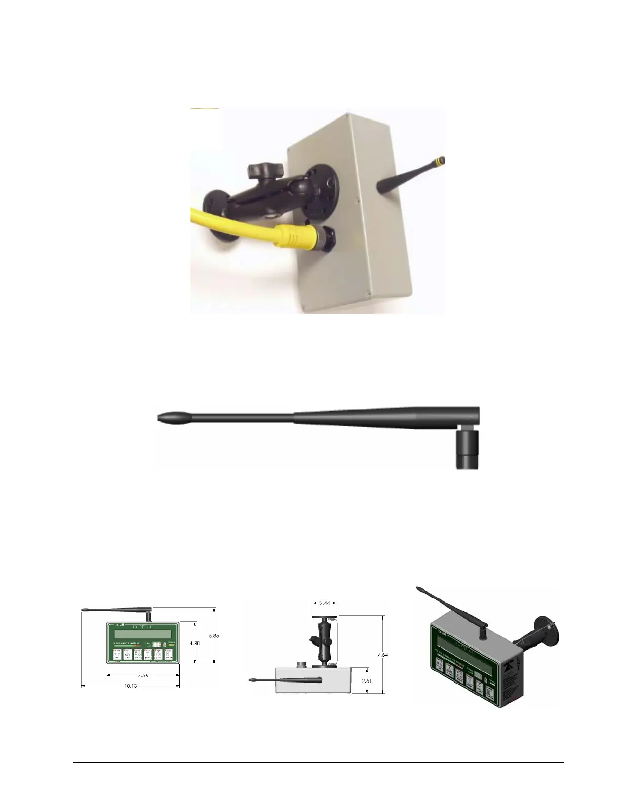
Antenna Position
For optimal performance the antenna should be positioned on its side such that it is parallel to the
sensor antennas (but not pointing directly to or directly away from them).
• Adjust antenna position with the articulating base.
• The antenna must have 5 inches of clear space all around it.
• The antenna must have an unobstructed line of sight to all sensor antennas at all boom angles.
Fi
ure: Di
ole Half Wav
Elbow Antenna,
art
№
TA00
Figure: The power cable requires about 4 ½
in. behind the display to protect the connector
SkyAzúl, Equipment Solutions