22 The GS550 System
Power Supply and Lockout Connection
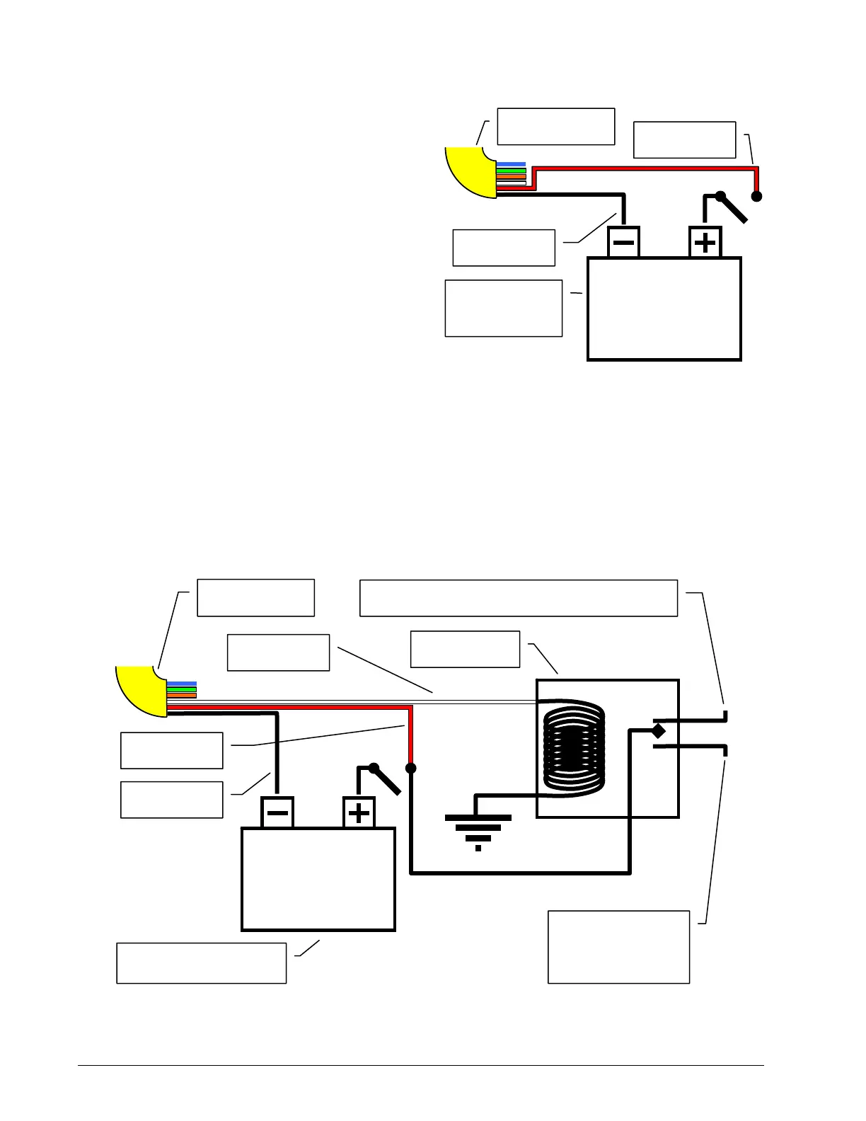
1. Connect the black wire (ground) to the
negative terminal of the crane battery or the
panel connection; alternatively bolt the
black wire to the body of the machine with a
¼ inch or 5/16 inch bolt. The ground con-
nection must be strong enough to sustain
3 amperes.
2. Connect the red wire to a fused accessory
source, rated at least 3 amperes, that sup-
plies +12 or +24 volts when the crane is on.
The GS550 will automatically detect the
voltage level and adjust itself.
3. Lockout number 1 (if required): connect the white wire to a Bosch relay coil. Connect the other
terminal of the relay to the ground. When operating properly the white wire will energize at the
battery positive level. Troubleshooting; if no voltage is present on the white wire remove the
load connected to the lockout. Current over 1.5 amperes on the white wire triggers an auto re-
settable fuse. Current flow will resume several seconds after the short circuit is eliminated.
4. Lockout number 2 (if required): the green wire functions in the same way as the white wire; see
above. The green wire lockout signal could be triggered by a different set of alarms than the
other lockout wires. See the Lockout Settings sub section of this manual.
n.c.
n.o.
co
Battery
+12 V or +24 V
Red wire
Black wire
Crane Power Supply
Yellow cable
White wire
Bosch relay
To valve coil if normally closed is required
To valve coil if
normally open is
required
Figure: Connection with white wire lockout and recommended Bosch rela
Battery
+12 V or +24 V
Red wire
Black wire
Crane Power
Supply
Figure: Connection without lockout
Yellow cable
SkyAzúl, Equipment Solutions