50 The GS550 System
Imbalance factor limit. The imbalance factor is the percent difference between the load
on one load sensor and the average load on the other three. The imbalance factor is calcu-
lated for each of the four load sensors and then compared to an adjustable limit. The de-
fault imbalance factor limit is 15%.
Imbalance minimum limit. Imbalance is not calculated when the four load sum is below
the imbalance minimum limit. Adjust this limit to avoid generating an imbalance alarm under
minimum load conditions (for example: with an empty container or with rigging only). The
default imbalance minimum limit is 1000 (pounds or kilograms depending on load display
units).
Program the imbalance sensor.
1. Press Menu → Next → Next → Next → Enter → Enter to go to the sensor list (4A1).
2. Press Next repeatedly to advance to the next available sensor position, usually follow-
ing the four load sensors and the sum load sensor.
3. The id can be left at 0, press Next.
4. The sensor type should flash; use Up and Down to select the sensor type Imbalance
sensor. Only one imbalance sensor is required to calculate imbalance for all four load
sensors.
5. Press Enter to save any changes.
6. Press Exit three times to return to the operation display.
7. Confirm the imbalance factor limit and the imbalance minimum limit in the limit menu.
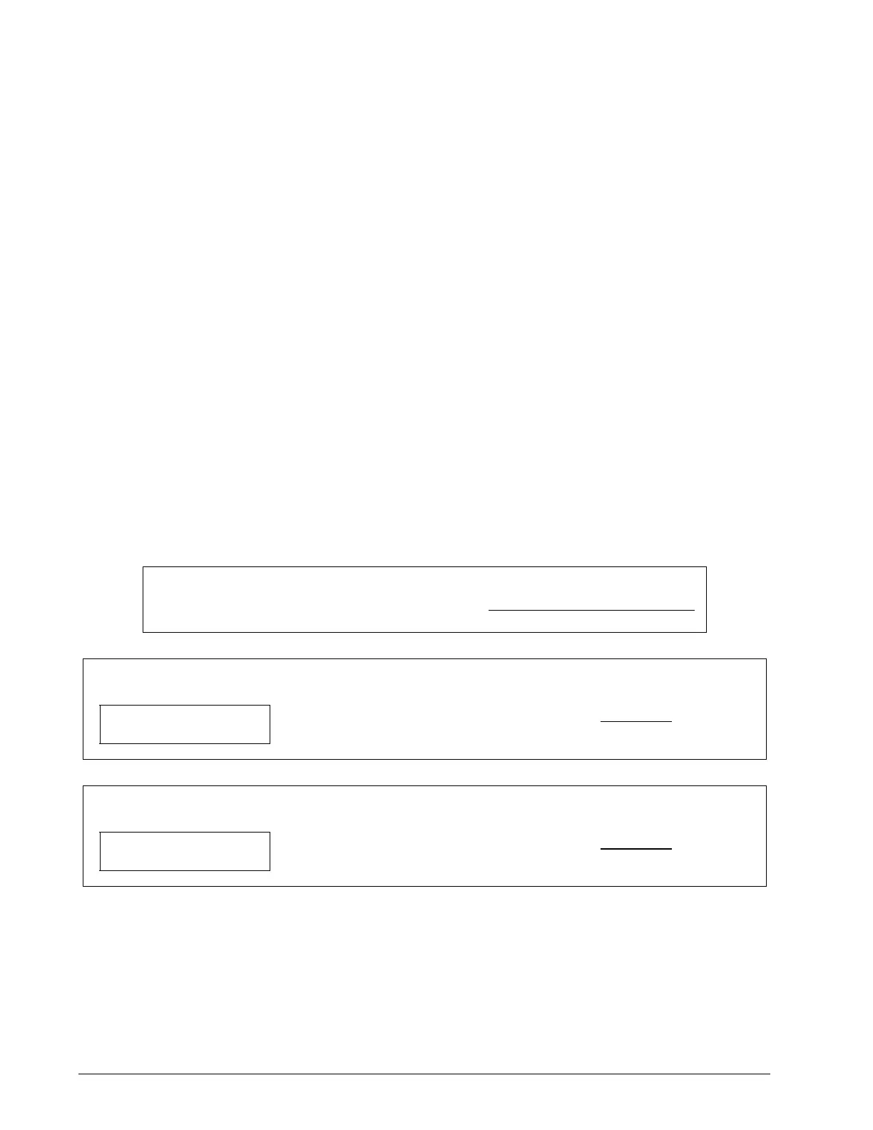
Examples:
Imbalance factor calculation for load sensor № 1
Load № 1 Imbalance Factor = 100 x
Average (Load 2, 3, and 4) – Load 1
Average (Load 2, 3, and 4)
If the imbalance factor limit is 15%, then the system is safe.
A 7500 B 8100
C 8000 D 8200
Load № 1 (A) Imbalance Factor = 100 X
8100 – 7500
8100
= 7.5 %
If the imbalance factor limit is 15%, then an imbalance alarm is generated.
A 6800 B 8100
C 8000 D 8200
Load № 1 (A) Imbalance Factor = 100 X
8100 – 6800
8100
= 16 %
Slack Rope
Systems programmed for four load sensors and four load sum indication can be programmed with
a slack rope sensor to warn against unwanted rope payout when the load touches down.
SkyAzúl, Equipment Solutions