48 The GS550 System
b. There must be direct unobstructed line of sight from the transmitter to the display; this
may not be required on cranes with a maximum boom length less than 100 feet (33 me-
tres).
c. The transmitter antenna must not be in contact with any metal object.
W
ARNING
! Do not weld in proximity to LSI sensor/transmitters.
2. Weld the mounting blocks where required.
3. Mount the load pin transmitter on the mounting blocks.
Load Pins, Line Riders and Compression
Cells: Calibration
Load pins, line riders and compression cells must be cali-
brated at installation and every time thereafter the installa-
tion, the load sensor or the load transmitter is changed.
Important! Do not recalibrate flat bar load links (part
numbers GC005, GC012, GC018, GC035, GC060,
GC100, and GC170).
This procedure requires two known weights. The first (light)
weight should be about 10% of load sensor capacity and not
less than 5%. The second (heavy) weight should be over
50% of capacity, and absolutely not less than 25%.
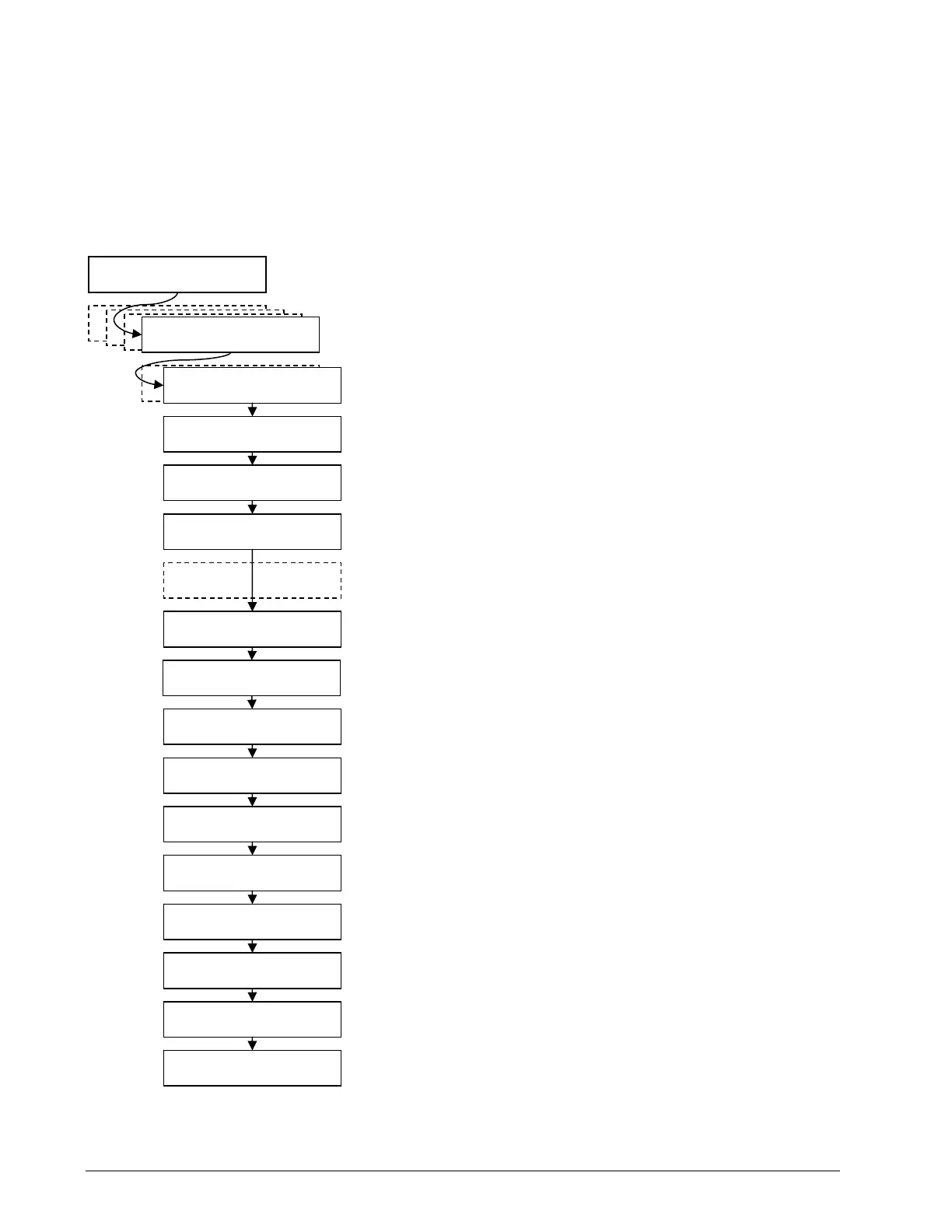
1. Press Menu → Next → Next → Next to go to menu 4)
Installation.
2. Press Enter → Next to go to menu 4B) Sensor Calibra-
tion.
3. Press Enter to go to the password page.
4. Use Back, Next, Up, and Down to enter the user pass-
word, and then press Enter to go to 4B1) Automatic
Value Calibration Wizard.
5. Press Enter to go to 4B1A).
6. Use Back and Next to select the load sensor, and then
press Enter to confirm communication with the sensor is
possible.
7. Press Next to start the wizard.
8. Use Up and Down to adjust the actual parts of line on the
load sensor, and then press Next.
9. Note the units that will be used during the calibration
wizard, and then press Next.
10. Lift the first (lighter) known load, and then press Next.
11. Use Up and Down to adjust the load value displayed to
equal the actual known load lifted, and then press Next.
12. Lower the first load, lift the second (heavier) known load,
and then press Next.
13. Use Up and Down to adjust the load value displayed to
equal the actual known load lifted, and then press Next.
14. Note the new trim value, and then press Next.
Operation Display
1) Parts of Line
2) Crane Rigging
3) Display Settings
Enter user password:
aaa
4B1) Automatic value
calibration wizard
4B1A) No. x id: Gxxxxx
Load sensor
Communicating with
remote sensor
Load calibration
wizard. Press Next.
2/9) Confirm current
unit: (lb, kg, T, t)
3/9) Lift known
load No. 1: xxxx
4/9) Adjust actual
load No. 1: xxxx
5/9) Lift known
load No. 2: xxxx
6/9) Adjust actual
load No. 2: xxxx
7/9) Calib Result
Trim: xxx
8/9) Calib Result
Scale: x.xxxx
9/9) Press Enter to
save calib in sensor
4A) Sensor List
4) Installation
4B) Sensor Calibration
Figure: The automatic load
calibration wizard.
1/9) Enter actual
parts of line: 1
SkyAzúl, Equipment Solutions