30 The GS550 System
e. The angle sensor must have a clear line of sight to the cabin mounted display.
f. The angle sensor antenna must not contact a metal object.
2. Install the welding pads; keep the angle sensor well removed from the weld site and any
connecting metal objects while welding.
3. Mount the angle sensor to the weld pads with the screws and washers provided.
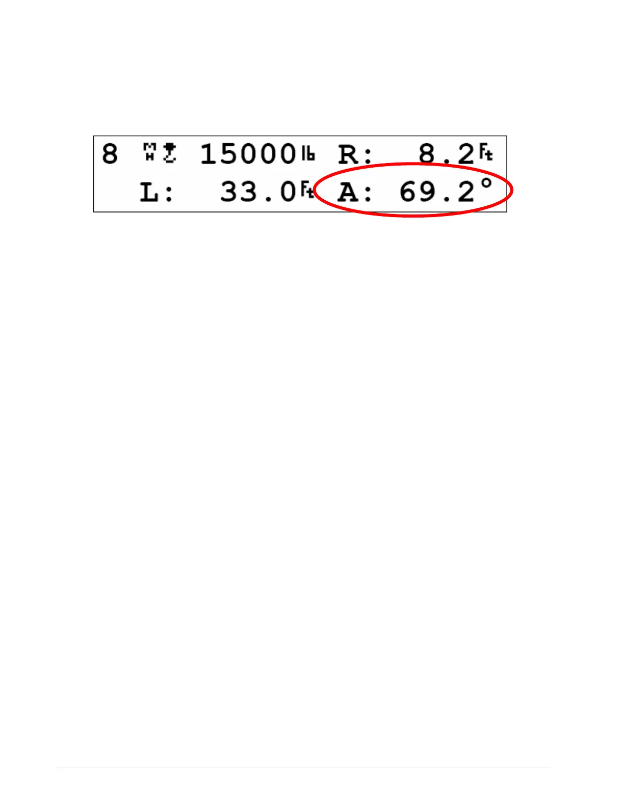
4. Verify angle indication on the GS550 LCD.
5. If the angle displayed by a GS010-01 boom angle sensor is a high negative value, then tilt the
angle sensor up over 45 degrees, and then tilt back down to horizontal. The GS010-01 boom
angle sensor will automatically detect on which side of the boom it is installed and correct angle
indication accordingly.
Tip: To enable crane functions when alarm conditions are present, press Bypass for 10 seconds to
enter the “Rig Mode”. Press Bypass once to exit.
Angle Calibration Procedure № 1: Mechanical Set-Up
1. Level the boom such that it is perfectly horizontal; use a high quality bubble or digital angle
sensor. If the GS550 display indicates 0.0 degrees then angle calibration is complete; if not
then continue to step 2.
2. For GS011 angle/length sensors only: Carefully remove the cover of the LS101 cable reel.
3. Loosen the mounting screw in the slotted hole of the angle sensor mounting plate.
4. Pivot the angle sensor slightly until angle indication is correct.
Tip: When the angle sensor is moved very slowly, it may take several seconds to see an update at
the GS550 display. Instead move the sensor up a couple of degrees, and then bring it back down
to where it should be. The small light on the angle sensor flashes when it transmits a new value to
the display.
Angle Calibration Procedure № 2: Correct with the GS550
Calibrate angle indication by adjusting the trim (offset) value in the GS550 display; the GS550 will
then communicate the updated trim value to the sensor.
1. Position the boom at a precisely known angle.
2. Press Menu → Next → Next → Next to go to 4) Installation.
3. Press Enter → Next to go to 4B) Sensor Calibration.
4. Press Enter to go to the password page.
5. Use Back, Next, Up and Down to enter the user password, and then press Enter → Next to
go to 4B2) Manual parameter calibration.
6. Press Enter to go to page 4B2A)
7. Use Back and Next to select the angle sensor to be calibrated.
Figure: Typical operation page with boom angle indicatio
SkyAzúl, Equipment Solutions

 Loading...


