32 The GS550 System
1. Verify the GS050 anti-two-block switch is programmed to the GS550 display. Switches shipped
with displays are pre-programmed in the factory. Test: if the switch has been programmed to
the display then the display will go in to two-block alarm when the wire rope of the switch is re-
leased. Press Bypass to silence the alarm until the next two-block event or simulation. If the
switch has not been programmed to the display, this should be done before proceeding to step
2. See the sub-section How to Add a Sensor to the GS550 in this manual.
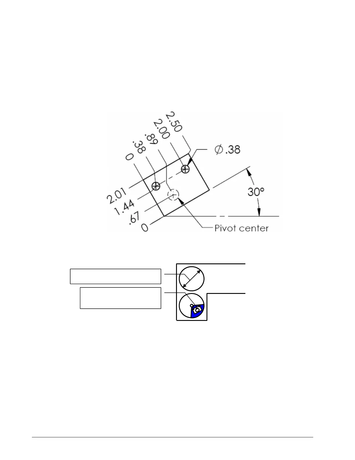
2. Position the sensor mounting bracket. To ensure that the sensor can pivot securely on the
mounting bracket throughout the full range of boom angle, the mounting bracket must be posi-
tioned at a 30° from horizontal with the boom parallel to the ground and such that the locking
pin of the mounting bracket points up. Bolt or weld securely.
If the head sheave diameter is between 8 and 16 inches (20-41 centimetres) then two mounting
brackets will be required to permit both live and dead end mounting.
Figure: Bracket footprint and orientation. All dimensions are in inches.
← Boom Tip
Mount bracket below and
behind sheave centre.
Up to 8 in. (20 cm) diameter
Boom base →
Figure: Ant
tw
block switch placement on a telescopic boo
SkyAzúl, Equipment Solutions