Installation 33
For live end mounting on multiple sheave blocks with sheaves greater than 16 inches
(41 centimetres) in diameter consult your service representative.
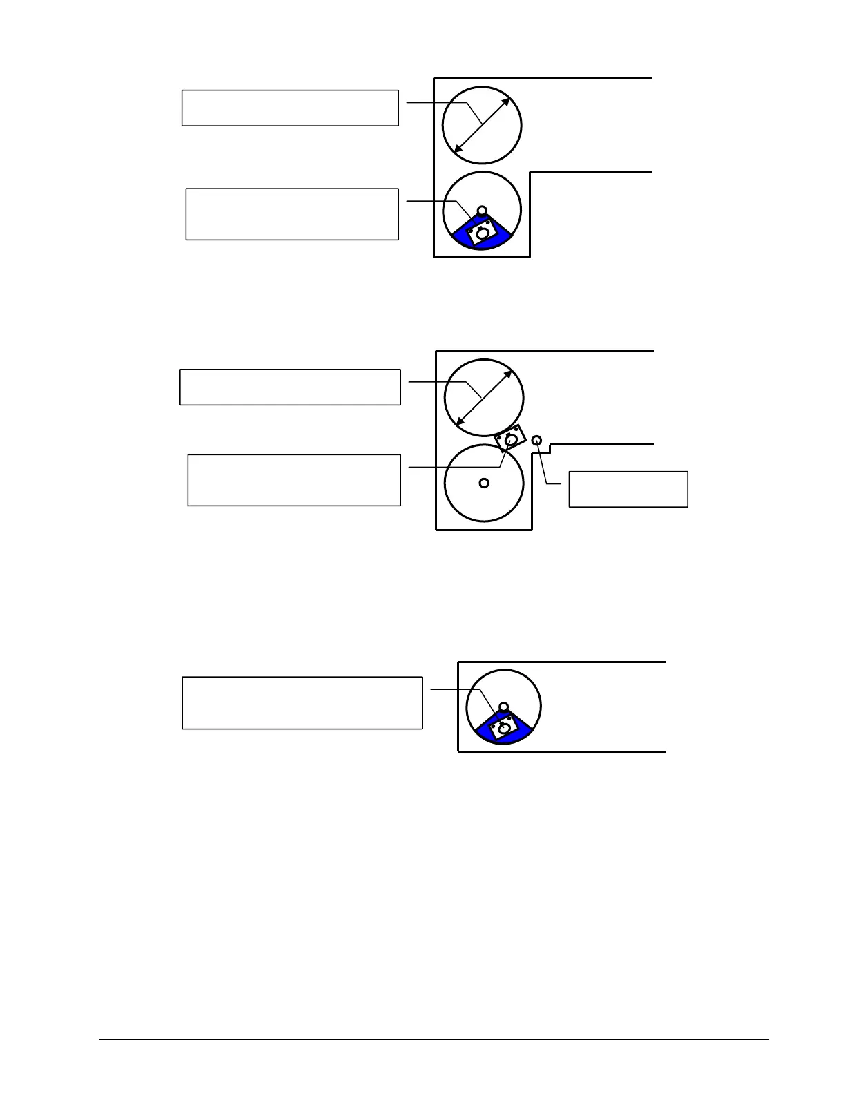
For fast line weight installation place the anti-two-block switch mounting bracket directly below
the sheave center as low and as close to the edge of the sheave as possible. Place the fast line
weight mounting bracket on the opposite side of the sheave with the chain hole pointing down
and lined up opposite the pivot of the anti-two-block switch mounting bracket.
Mount bracket 4 in. (10 cm)
below sheave centre.
8-16 in. (20-41 cm) diameter
Boom base →
Figure: Ant
tw
block switch placement for live end mounting on a lattice boom,
Figure: Ant
tw
block switch placement for dead end mou
ing on a lattice boo
Mount bracket 4 in. (10 cm)
in front of the dead end pin.
8-16 in. (20-41 cm) diameter
Boom base →
Dead end pin
Mount bracket 2-4 in. (5-10 cm)
below sheave centre.
Boom base →
Figure: Jib, rooster or other extension, anti-two-block switch
placement for single part of line operation only
SkyAzúl, Equipment Solutions