p/n 18603-001, Rev. C LTV
®
1200/1150 Ventilator Service Manual Page 8-37
Tubing Removal/Replacement Instructions
Parts required for replacement: Tools required:
• None
Replace if damaged:
• Flexible tubing
41
• Elbow fitting (1) P/N 11592
• Elbow fitting (2) P/N 10958
• Tee fitting (3) P/N 18186-001
• Wye fitting (1) P/N 18185-001
• Plug fitting (1) P/N 18187-001
• Restrictor (1) P/N 18551-022
• Filter (1) P/N 18552-001
• Cable assembly (1) P/N 18530-001
• Grounded anti-static wrist strap
• Measuring tool (Calipers, Ruler, etc) 0” thru 11” range
• Pliers - long round nose, smooth jaws – ESD safe
• Torque Driver(s) – 20 in-oz thru 120 in-oz range with;
• # 1 Phillips Bit
• 1/4” Nut Driver
To remove internal flexible tubing:
1) Remove the ventilator back panel and disconnect the internal battery cable from
the Power PCBA (see instructions on page 8-28).
2) Review and become familiar with the existing tubing configuration prior
to
removing individual tubes and strictly adhere to the replacement instructions when
reattaching them (point to point and layering).
3) Remove only the tubing or components that needs replaced, upgraded, or removed
in order to access other components requiring service.
• all tubing is interference fit onto individual ports, elbows or tees and can be
removed by gently twisting the tube and pulling it off.
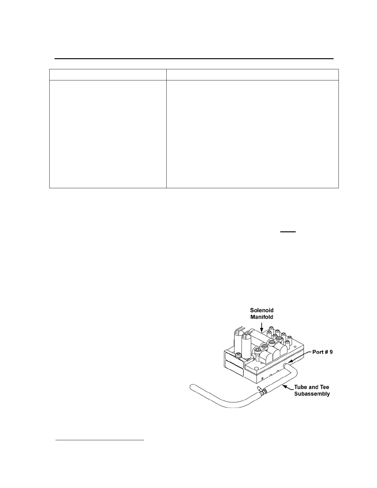
4) To avoid damaging tubing and
expedite replacement;
• do not remove the Tube
and Tee subassembly
attached to solenoid
manifold port # 9 (side
port) until either the
Analog PCBA or Solenoid
Manifold is removed and
then only when necessary
to replace individual tubes
or components of the
subassembly itself
41
See Tubing Table in this chapter for detailed descriptions and part numbers of individual flexible tubes.