Page 8-116 LTV
®
1200/1150 Ventilator Service Manual p/n 18603-001, Rev. C
Solenoid Manifold Assembly
Parts required for replacement: Tools required:
• Solenoid Manifold Assembly P/N 18528-001
• Phillips screwdriver with torque meter
• 1/4” Nut Driver adapter for torque wrench
• Grounded anti-static wrist strap
• Torque screwdriver (120 in-oz/0.84 Nm)
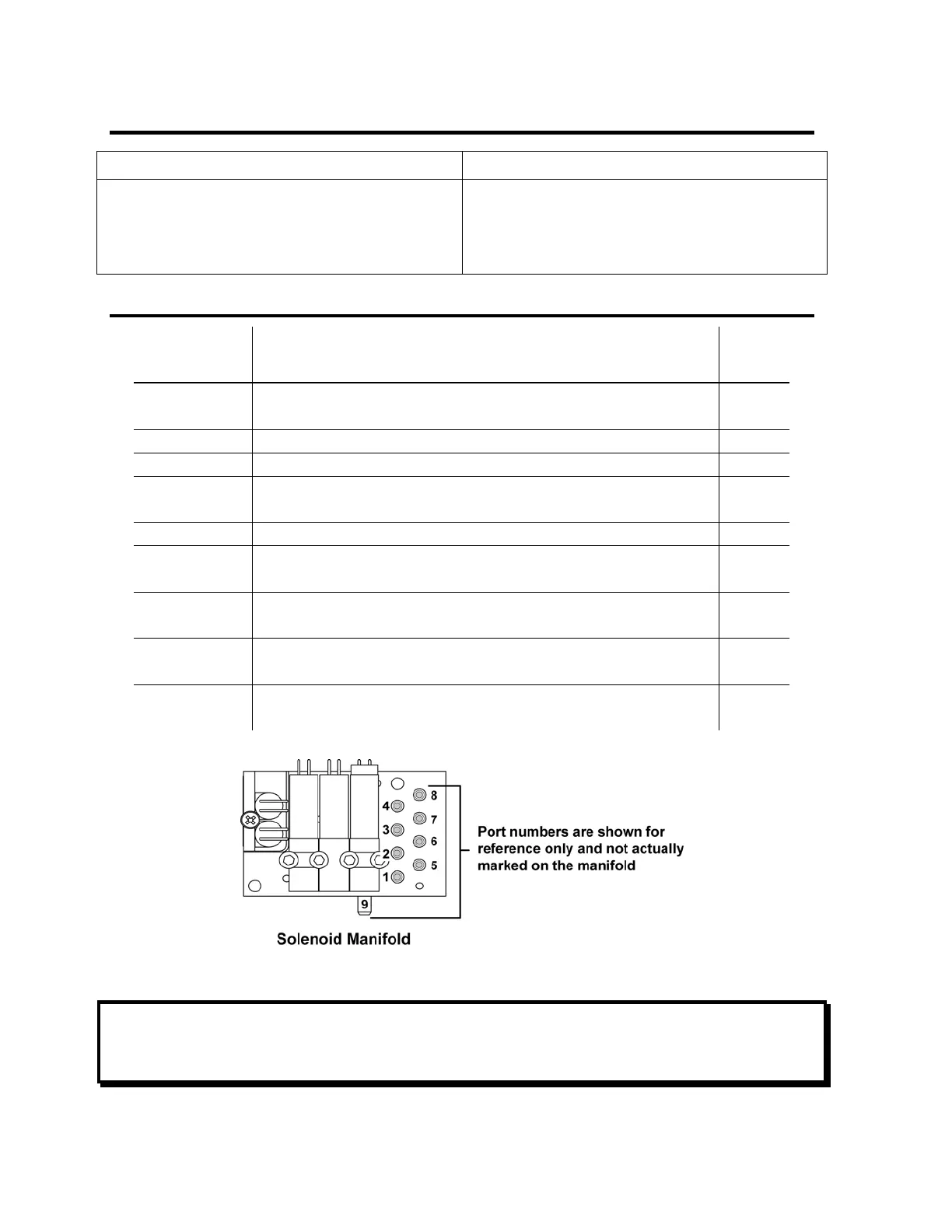
Solenoid Manifold Tube Routing Table
Solenoid
Manifold
Port Number
Port Tubing Routed
Tubing
P/N
#1 Onto the high pressure port on the Valve Differential Transducer (PT7)
• through a tee & elbow subassembly
11834
#2 Onto the Flow Differential Transducer (PT4) 10458
#3 Onto the Airway Pressure Transducer (PT6) 11834
#4 Onto the side panel low pressure Flow Transducer port
• male Luer fitting on outside of panel
11834
#5 From the Flow Valve (clear tubing) 10455
#6 Onto side panel Exhalation Valve port
• barbed fitting on outside of panel
11834
#7 Onto the Flow Differential Transducer
• through a tube & elbow subassembly
11834
#8 Onto the side panel high pressure Flow Transducer port
• female Luer fitting on outside of panel
11834
#9 Onto Accumulator port A
• through a tube & tee subassembly
11834
NOTE
Tubing Configurations - When disconnecting tubes, note their positions and review the
internal flexible tube routing tables, instructions and diagrams beginning on page 8-33.