p/n 18603-001, Rev. C LTV
®
1200/1150 Ventilator Service Manual Page 8-63
Fan Assembly
Parts required for replacement: Tools required:
• Fan Assembly P/N 10675
Replace if damaged:
• 5/8" Flat-head Screw (2) P/N 10499
• Nut (2) P/N 10342
• Phillips screwdriver with torque meter
• Grounded anti-static wrist strap
To replace the fan assembly:
1) Remove the back panel of the ventilator and disconnect the internal battery cable (see page
8-28).
2) Disconnect the fan connection from the power board. Care should be taken to be sure the
DIP switch settings are not changed. DIP switches are located directly below the fan
assembly.
3) Remove the left soft side.
4) Remove the 2 screws and nuts holding the fan assembly.
5) Remove the fan assembly.
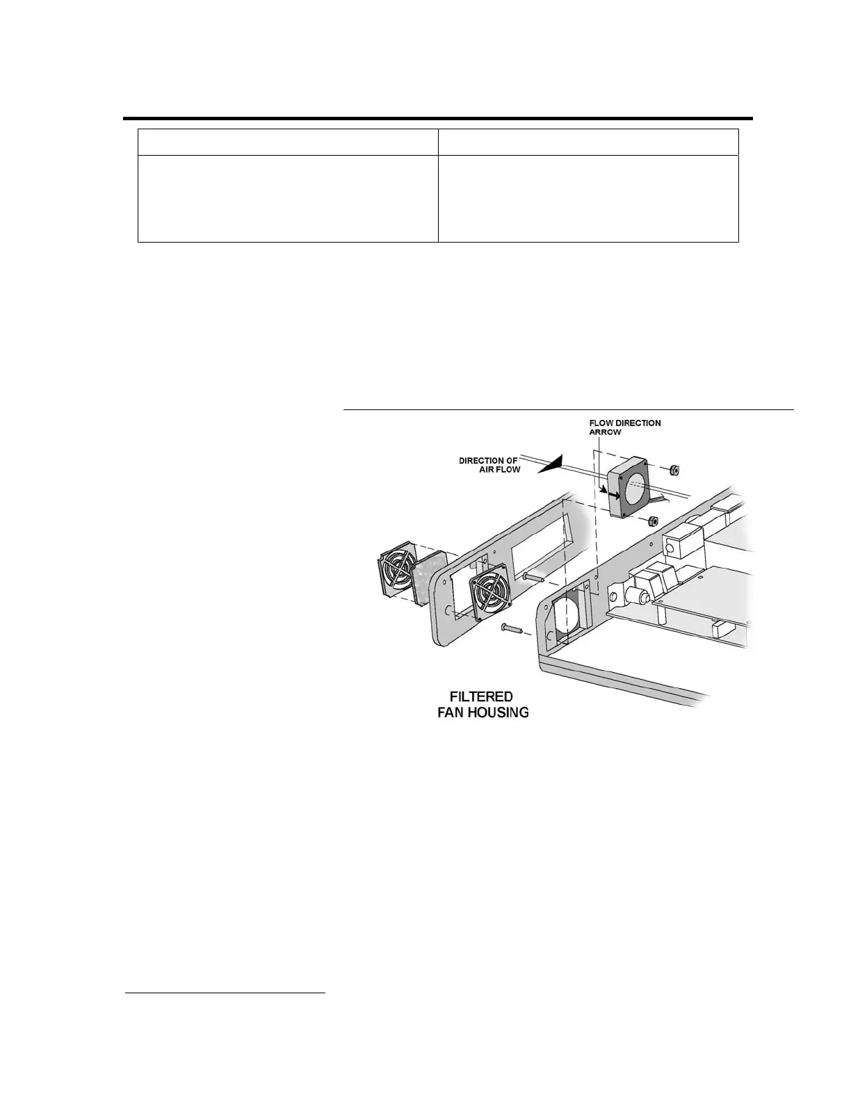
6) Install the new fan
assembly oriented so the
fan label faces the inside of
the vent and the fan wires
are in the corner closest to
the power board. Flow
direction indicator
should be directed
towards the inside of the
unit.
7) Replace the 2 screws and nuts holding the fan assembly in place. Screws should be torqued
to 40 in-oz (0.28 Nm). Care should be taken to be sure the DIP switch settings are not
changed. DIP switches are located directly below the fan assembly.
8) Connect the 2-wire connector from the fan to the power board. The connector is keyed to fit
in only one direction and will snap into place when properly connected.
9) If the fan grill bracket has been removed, replace it in the left soft side and replace the left
soft side. Replace the fan filter and fan filter grill.
10) Install an O
2
Sampling Tube
45
. See Back Panel, Reinstallation in Chapter 8 – Component
Removal and Replacement for detailed instructions.
11) Reconnect the battery and replace the back panel (see page 8-29).
45
O
2
Sampling Tube, P/N 10544, ~10.0” long, 0.125” O.D. X 0.079 I.D. clear polycarbonate tubing.