p/n 18603-001, Rev. C LTV
®
1200/1150 Ventilator Service Manual Page 8-65
Flow Valve Assembly
Parts required for replacement: Tools required:
• Flow Valve Assembly P/N 10019
• Silicone Gel Lubricant P/N 10123
46
• Thermistor Cable P/N 11399
Replace if damaged:
• Sealing Gasket P/N 10175
• 1 3/4" Pan-head Screw (2) P/N 10434
• Phillips screwdriver with torque
meter
• Grounded anti-static wrist strap
• Flow Valve Insertion Tool
37
(Mylar) P/N 14206
To remove the flow valve assembly:
1) Remove the ventilator back
panel and disconnect the internal
battery cable from the power
board (see instructions on page
8-28).
2) Disconnect the 4-wire flow valve
connector from the motor board.
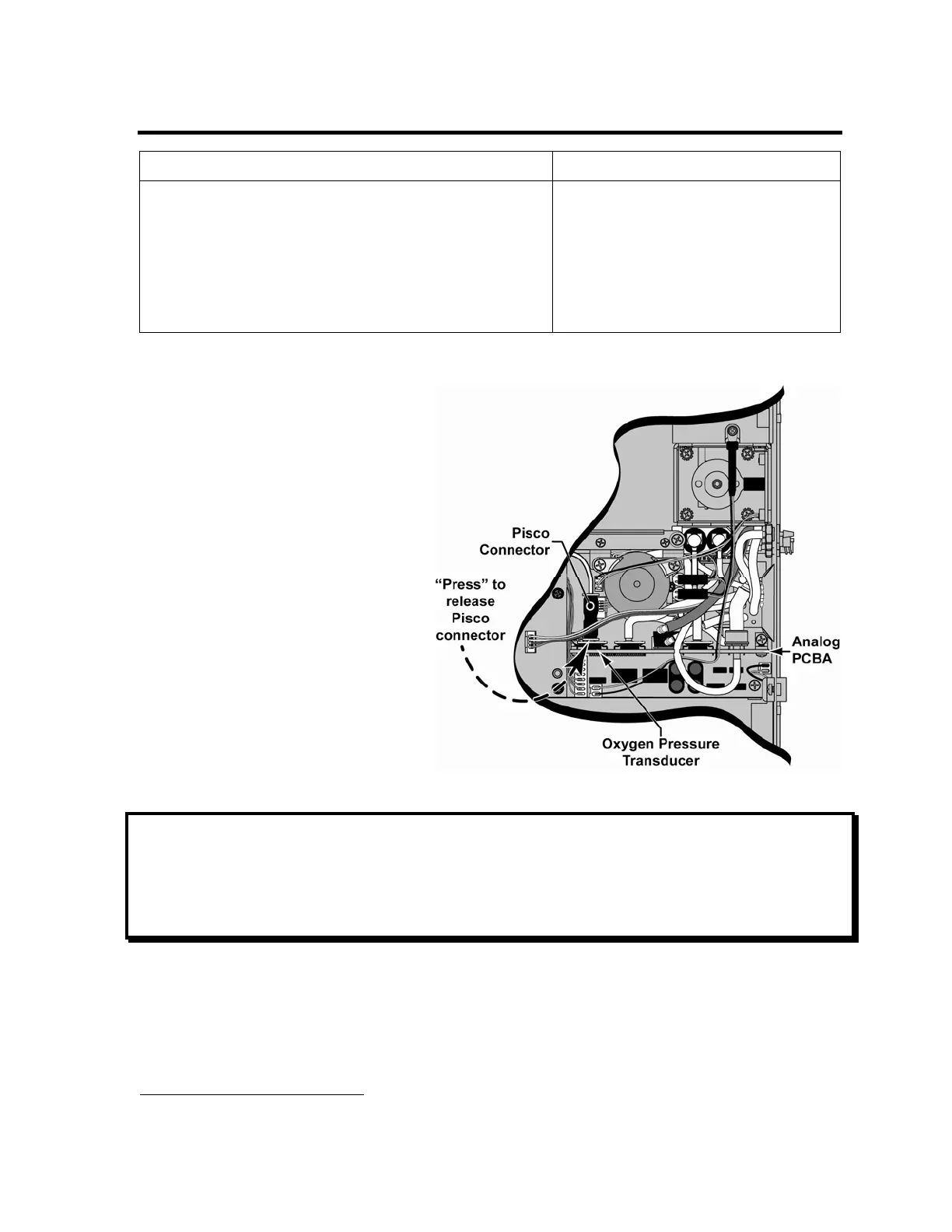
3) Disconnect the Pisco connector
from the oxygen pressure
transducer on the analog board
as shown (LTV
®
1200 only).
4) Disconnect the 3-wire flow valve
connector from the power board.
5) Disconnect the orange flow valve
tube from the analog board and
the tube connecting the flow
valve to the solenoid manifold at
port #5.
NOTE
Tubing Configurations - When disconnecting tubes, note their positions and review the
internal flexible tube routing tables, instructions and diagrams beginning on page 8-33.
If tubing needs to be replaced, consult the tables and instructions in Internal Flexible Tubing
beginning on page 8-33 for tubing diameters, lengths and routing diagrams.
46
The Silicone Gel Lubricant and Flow Valve Insertion Tool are available separately, or as part of the
Maintenance and Calibration Kit, P/N 11566.