Page 8-60 LTV
®
1200/1150 Ventilator Service Manual p/n 18603-001, Rev. C
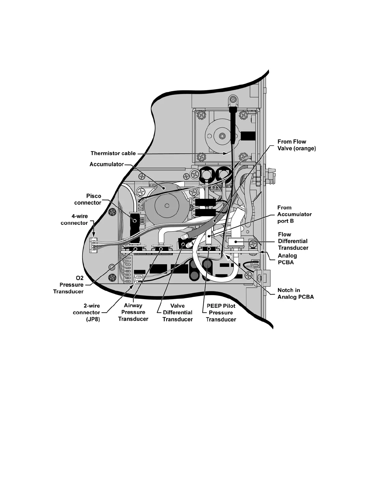
Analog board installation:
1) Insert the new analog board and secure with the two green mounting screws.
Screws should be torqued to 60 in-oz (0.42 Nm).
2) Reconnect the Pisco connector to the oxygen pressure transducer (LTV
®
1200 only).
3) Reattach the 6 flexible tubes to the new analog PCBA following the internal flexible tube
routing tables, diagrams and instructions on page 8-33.
• To the valve differential transducer (high side) from the tee fitting to port #1 of the solenoid
manifold
• To the pilot pressure transducer from port B of the accumulator
• To the flow differential transducer (large diameter port) from port #7 of the solenoid
manifold
• To the flow differential transducer (small diameter port) from port #2 of the solenoid
manifold (through the notch in the analog board).
• To the airway pressure transducer from port #3 of the solenoid manifold
• To the valve differential transducer (low side, furthest from the board) from the flow valve
(orange tube).