p/n 18603-001, Rev. C LTV
®
1200/1150 Ventilator Service Manual Page 8-75
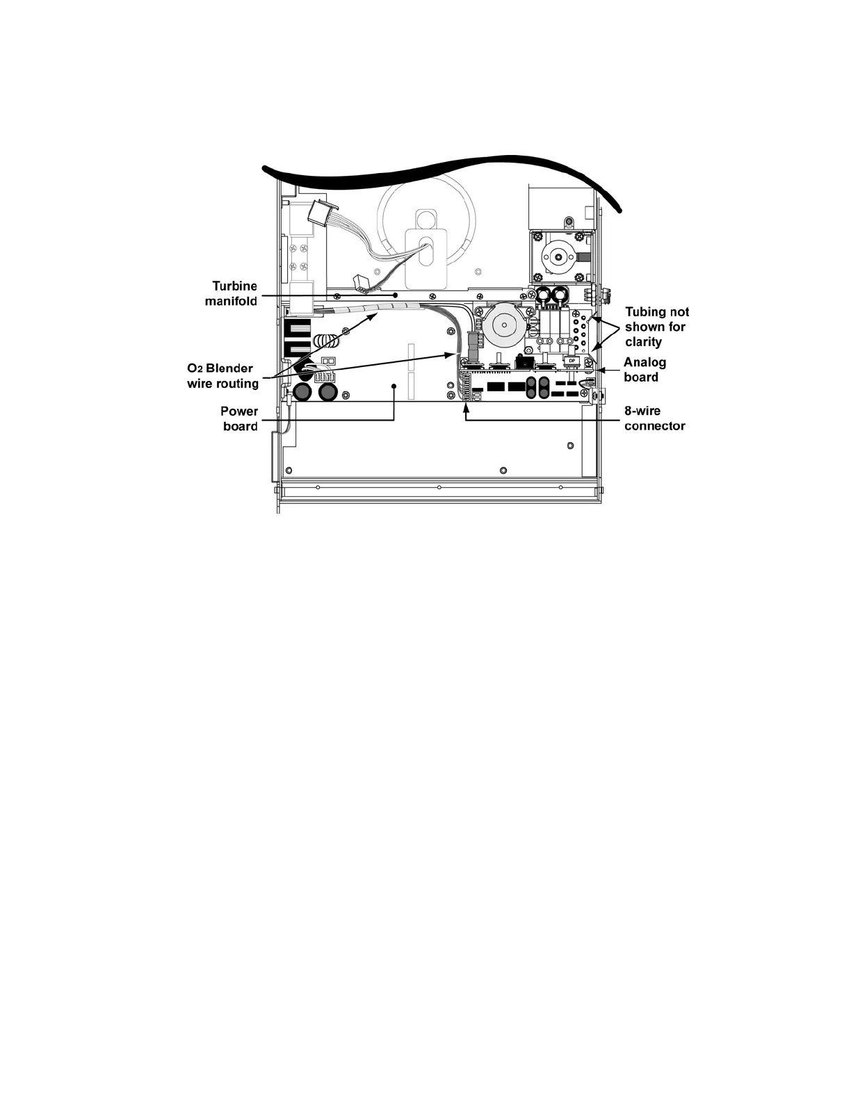
10) Reconnect the 8-wire oxygen blender connector to the power board (LTV
®
1200 only).
11) Ensure that the flexible tube from port B on the accumulator is tucked between the purge
solenoids and the turbine manifold. Reattach the turbine manifold spacer to the turbine
manifold using the four (4) 7/16” pan head screws (P/N 10433). Torque to 20 in-oz (0.14
Nm).
12) Reattach the solenoid mount assembly using one .125 ID x .3125 OD washer (P/N 18032-
001) and one 4-24 x 3/8” pan head screw (P/N 17682-001). Torque the screw to 120 in-oz
(0.84 Nm).
13) Reattach the accumulator to the spacer using two (2) 7/16” pan head screws P/N 10433.
Screws should be torqued tightened to 60 in-oz (0.42 Nm).
14) Replace the motor board. Use care when aligning the pass through connectors (see
instructions on page 8-90).
15) Reinstall the flow valve assembly and reconnect the orange and clear flow valve tubing (see
instructions on page 8-65).
16) Reconnect the 3-wire flow valve connector to the power board. The connector is keyed to fit
in only one direction and will snap into place when properly connected.
17) Reconnect the Pisco connector to the oxygen transducer on the analog board
(LTV
®
1200
only)
.
18) Reconnect the 4-wire connector from the flow valve and the 3-wire and 5-wire connectors
from the turbine to the motor board. The connectors are keyed to fit in only one direction
and will snap into place when properly connected.
19) Reconnect the 2-wire flow valve thermistor cable and the 4-wire flow valve connector to the
power board.