p/n 18603-001, Rev. C LTV
®
1200/1150 Ventilator Service Manual Page 6-11
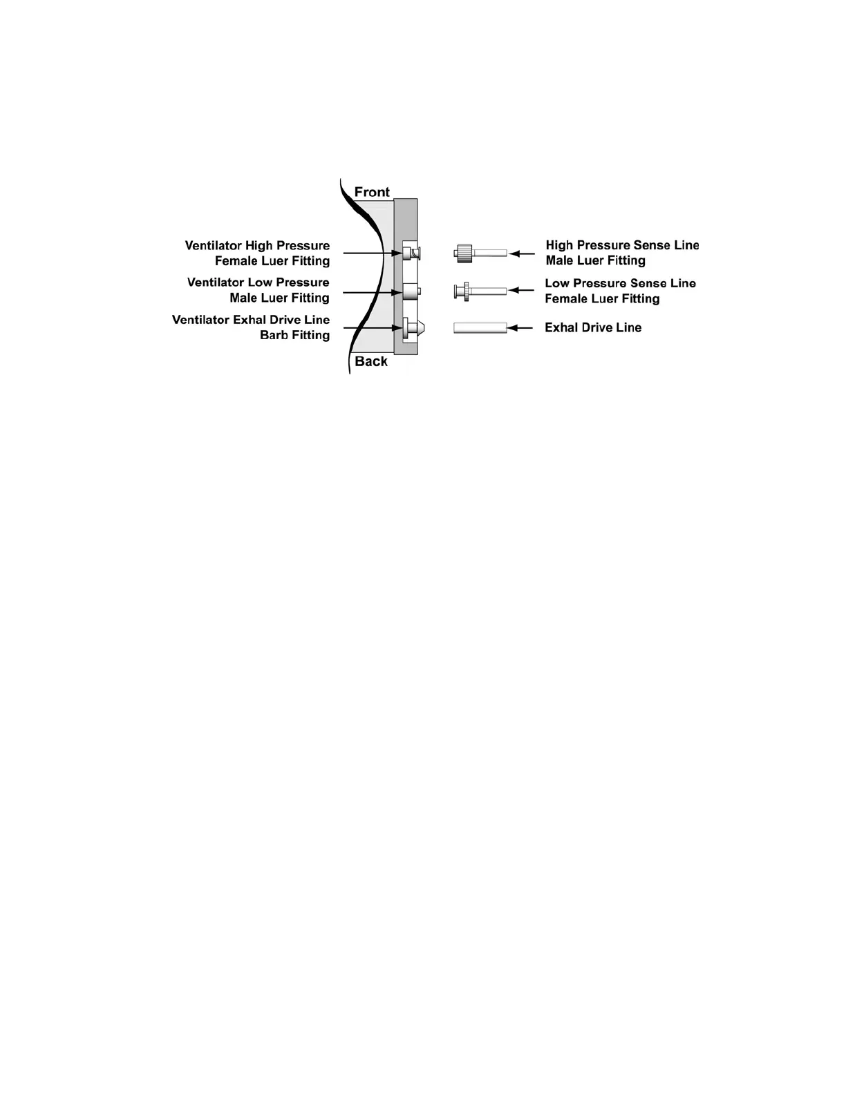
2) Connect the female Luer fitting from the calibration syringe assembly to the low pressure
male Luer fitting. Pinch off the tubing on the calibration syringe assembly to the male
Luer fitting, and increase and maintain the pressure at 30.0, ± 0.2 cmH
2
O.
Observe the numbers displayed in the Tidal Volume setting window. When the
displayed value is stable, press Select.
Record that value on the Calibration Worksheet.
FD 0
C
M
H
2
O is displayed.
3) Disconnect from the ventilator so the connection is open to ambient room air. Observe
the numbers displayed in the Tidal Volume setting window. When the displayed value is
stable, press Select.
Record that value on the Calibration Worksheet.
FD 30
C
M
H
2
O is displayed.
4) Connect the male Luer fitting from the calibration syringe assembly to the high pressure
female Luer fitting. Pinch off the tubing between the calibration syringe assembly and the
female Luer fitting, and increase and maintain the pressure at 30.0, ± 0.2 cmH
2
O.
Observe the numbers displayed in the Tidal Volume setting window. When the
displayed value is stable, press Select.
Record that value on the Calibration Worksheet.
FD 0
C
M
H
2
O is displayed.
5) Disconnect from the ventilator so the connection is open to ambient room air. Observe
the numbers displayed in the Tidal Volume setting window. When the displayed value is
stable, press Select.
Record that value on the Calibration Worksheet.
FD 80 ± 70 AD is displayed.