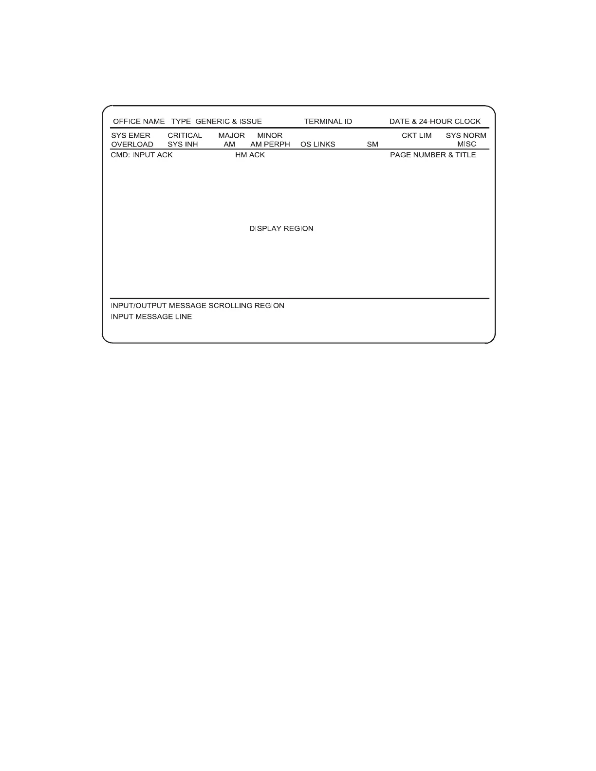
The identification line is present at all times and displays the office name, system
type, and the current date and time.
The system status display provides an indication of the overall status of the office.
This includes:
• Individual unit status
• Abnormal load conditions
• Significant controls in effect
• Alarms and other abnormalities.
The various conditions are shown in distinctive graphics and type faces.
The color video display at the MCC uses a variety of colors to indicate the status of
individual units in the DRM.
The control and display area is provided to give the maintenance personnel the
interface necessary to operate and maintain the system. This area displays
information pertinent to the office and provides the controls for maintaining and
operating the system.
The various screen formats are referred to as control and display pages. Each control
and display page shows the operating condition and possible input commands for each
subsystem. An index page is provided to allow quick access to the display pages. A
blank page is displayed whenever other control and display information is not
required. For additional information on the MCC display pages, see 235-105-110,
5ESS Switch System Maintenance Requirements and Tools. Figure 2-32 shows a
typical MCC display page.
Figure 2-31 — MCC Page Display Design
5ESS
®
SWITCH DISTINCTIVE REMOTE MODULE 235-200-150
Feburary 2007
Page 2-36 Issue 3.00O